Heat shield fastening structure for drum type washing machine with laundry drying function

a drum type, washing machine technology, applied in the direction of washing machines with receptacles, textiles and papermaking, other washing machines, etc., can solve the problems of deteriorating limited laundry positioned at the deepest place of the drum is not sufficiently dried, so as to enhance drying efficiency and drying performance, improve the air passage structure

Inactive Publication Date: 2005-12-01
LG ELECTRONICS INC
View PDF9 Cites 21 Cited by
  • Summary
  • Abstract
  • Description
  • Claims
  • Application Information

AI Technical Summary

Benefits of technology

[0033] An object of the present invention is to provide a drum type washing machine combined with a dryer and employing an improved air passage structure that can enhance the drying efficiency and drying performance, in particular, that can prevent a tub from being deformed due to heat of a heater of the drying duct.

Problems solved by technology

Due to the above construction, the related art drum type washing machine has various problems, for example, the drying efficiency and the drying performance are limited.
First, since the air fed to the inside of the drum is discharged through a front side of the tub under the circumstance that the air is not penetrated to a deep place of the drum, the laundry positioned at the deep place of the drum is not sufficiently dried.
To this end, the related art air passage structure deteriorates the drying efficiency and the drying performance.
Then, since the drying duct is in a fixed state and the gasket is shaken while the tub vibrates, the gasket may be worn or torn, which is disadvantageous.
Owing to the above reason, the high price gasket 8 having a low heat deformation property should be installed, which increases the manufacturing cost.
To this end, since the discharged hot air collides with the door glass to be subject to resistance, it is problematic that the hot air does not reach a deep position of the drum.

Method used


Image

  • Heat shield fastening structure for drum type washing machine with laundry drying function
  • Heat shield fastening structure for drum type washing machine with laundry drying function
  • Heat shield fastening structure for drum type washing machine with laundry drying function

Examples


Embodiment Construction

[0044] Reference will now be made in detail to the preferred embodiments of the present invention, examples of which are illustrated in the accompanying drawings.

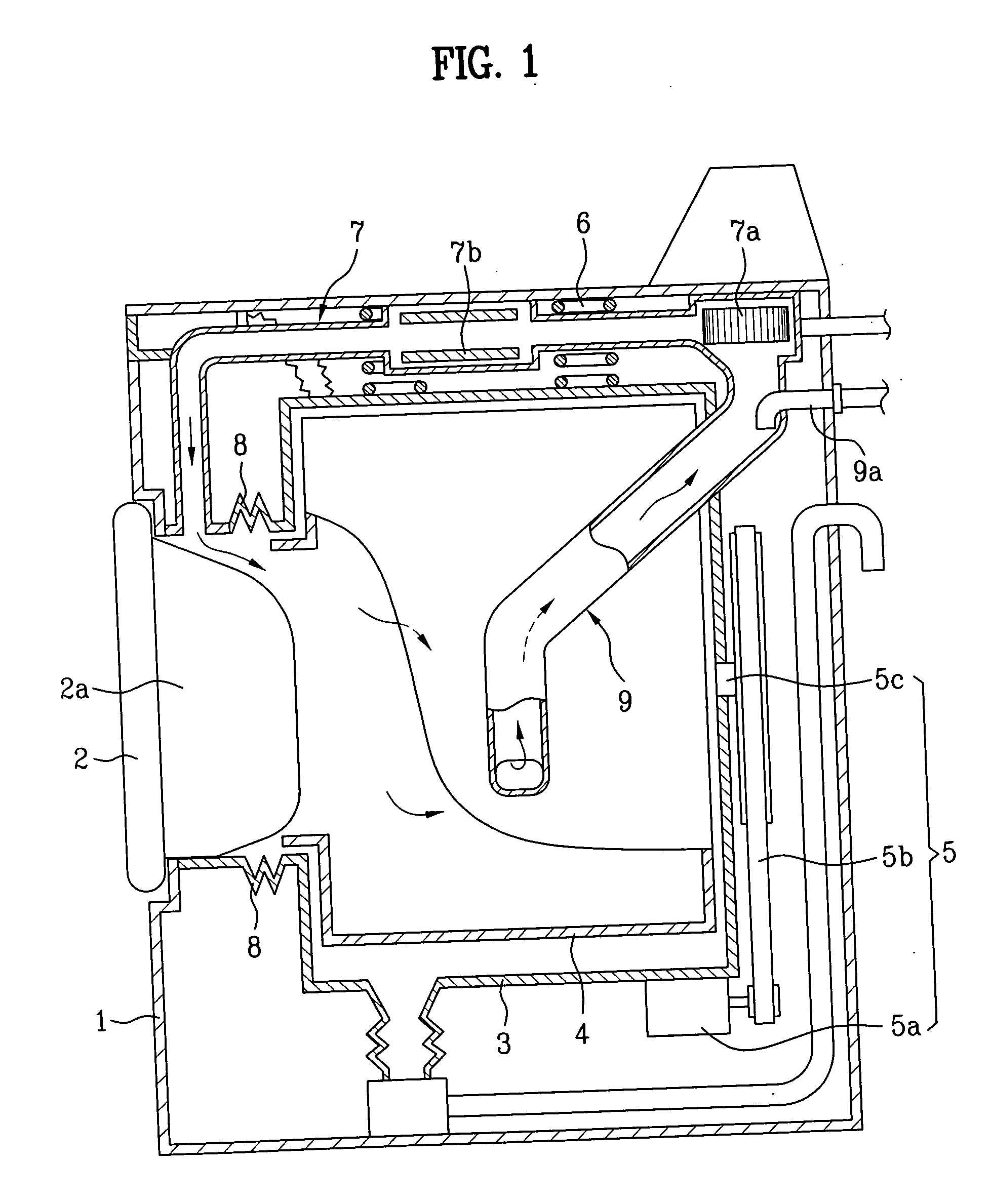
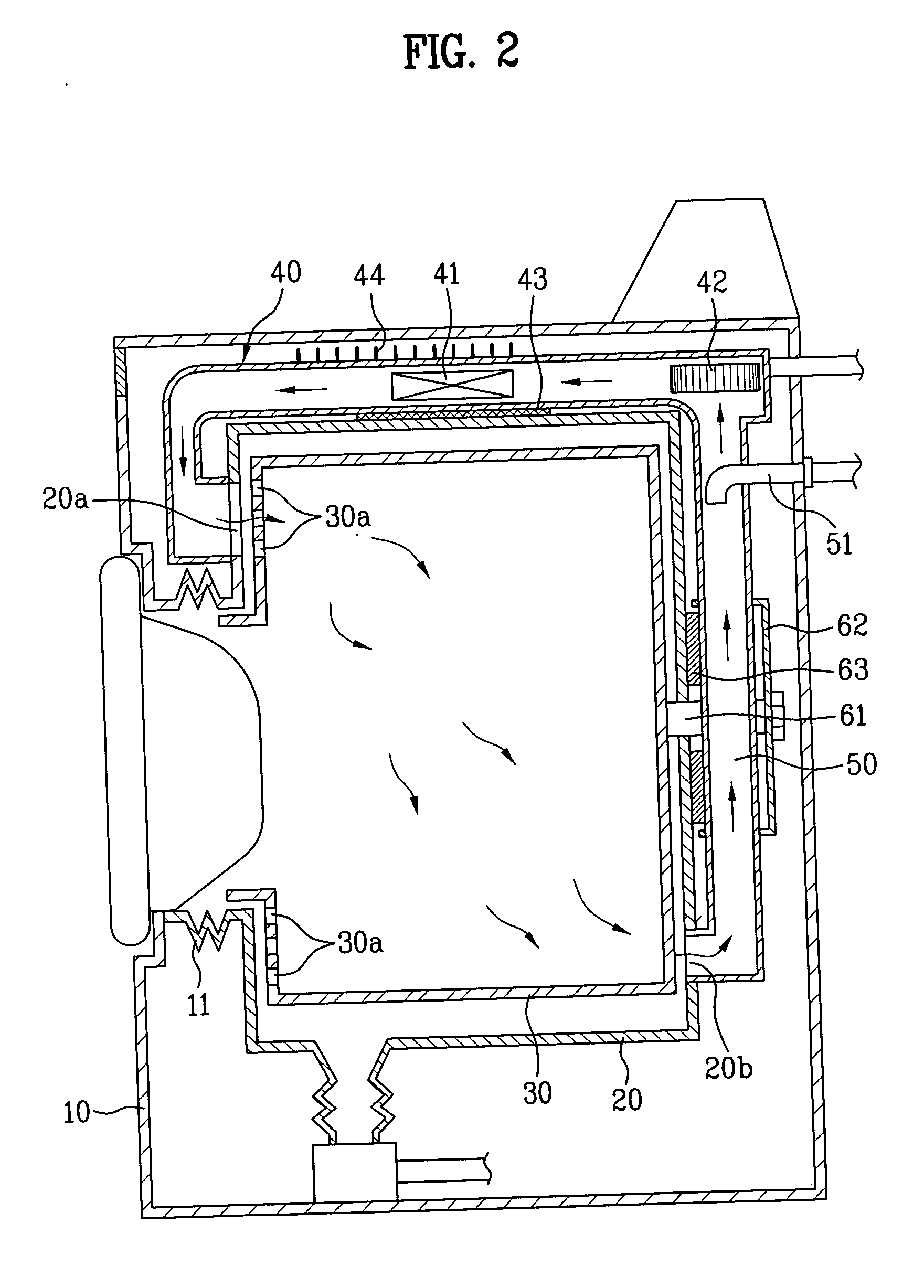
[0045]FIG. 2 is schematic side sectional view of a drum type washing machine according to the present invention, FIG. 3 is an exploded perspective view of a main part of FIG. 2, FIG. 4 is a schematic plane view of a heat shield according to the present invention and shows an installation state of the heat shield to a tub, and FIG. 5 is a sectional view of a main part in a heat shield fastening structure according to the present invention.

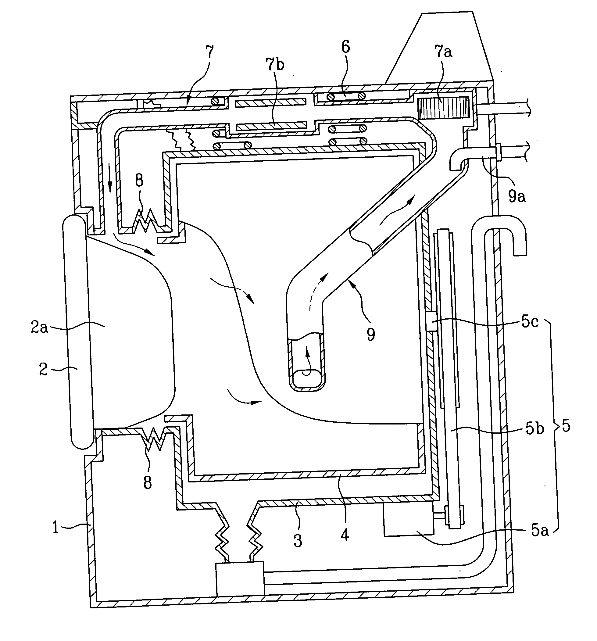
[0046] Referring to FIGS. 2 through 5, the washing machine includes a tub 20 installed inside a cabinet 10 to store washing water, and having a hot air inlet 20a formed at a front upper portion thereof and a hot air outlet 20b formed at a rear lower portion thereof, a drum 30 rotatably installed inside the tub 20 and having a plurality of hot air passing holes 30a formed at a front side t...


PUM


Abstract

Provided is a drum type washing machine combined with a dryer and employing an improved air passage structure that can enhance the drying efficiency and drying performance, in particular, that can prevent a tub from being deformed due to heat of a heater of the drying duct. The washing machine includes: a cylindrical plastic tub having a hot air inlet formed at a front upper portion thereof and a hot air outlet formed at a rear lower portion thereof; a drum rotatably installed inside the tub; a drying duct provided with a heater and a blower fan that are mounted on an inner air passage of the drying duct and fixed to an upper predetermined portion of an outer circumference of the tub; a condensation duct for removing moisture contained in hot air exhausted through the hot air outlet of the tub; and a heat shield interposed between the tub and the drying duct, for shielding heat of the drying duct from being transferred directly to the tub.

Description

[0001] This application claims the benefit of the Korean Application No. P2004-26740 filed on Apr. 19, 2004, which is hereby incorporated by reference. BACKGROUND OF THE INVENTION [0002] 1. Field of the Invention [0003] The present invention relates to a drum type washing machine, and more particularly, to a drum type washing machine combined with a dryer and employing a new air passage structure that can enhance the drying efficiency and drying performance. [0004] 2. Discussion of the Related Art [0005] In general, the drum type washing machine washes laundry by using friction between a drum rotated by a driving force of a motor and laundry under a state detergent, washing water, and the laundry are received in the drum. The drum type washing machine has advantages in that the laundry is almost not involved in damage and tangling between the laundries, and in that washing effects obtainable by beating and rubbing the laundry can be provided. [0006] A related art drum type washing m...

Claims


Application Information

Patent Timeline
Patent Type & Authority Applications(United States)
IPC IPC(8): D06F25/00D06F39/04D06F58/20D06F58/26
CPCD06F25/00D06F37/262D06F39/04Y02B40/00
Inventor BYUN, SANG TAEKIM, KWANG SOO
Owner LG ELECTRONICS INC
Why Eureka
Try Eureka