
Heat dissipation module with noise reduction

a heat dissipation module and noise reduction technology, applied in the direction of liquid fuel engines, semiconductor/solid-state device details, lighting and heating apparatus, etc., can solve the problems of heat dissipation design hitting a bottleneck, heat convection and heat dissipation design insufficient space inside the case housing of notebook pc, etc., to achieve the effect of reducing nois

Inactive Publication Date: 2005-12-01
QUANTA COMPUTER INC
View PDF5 Cites 3 Cited by
  • Summary
  • Abstract
  • Description
  • Claims
  • Application Information

AI Technical Summary

Benefits of technology

[0008] It is therefore an objective of the present invention to provide a heat dissipation module with a noise reduction function so as to reduce noise caused by strong airflow.
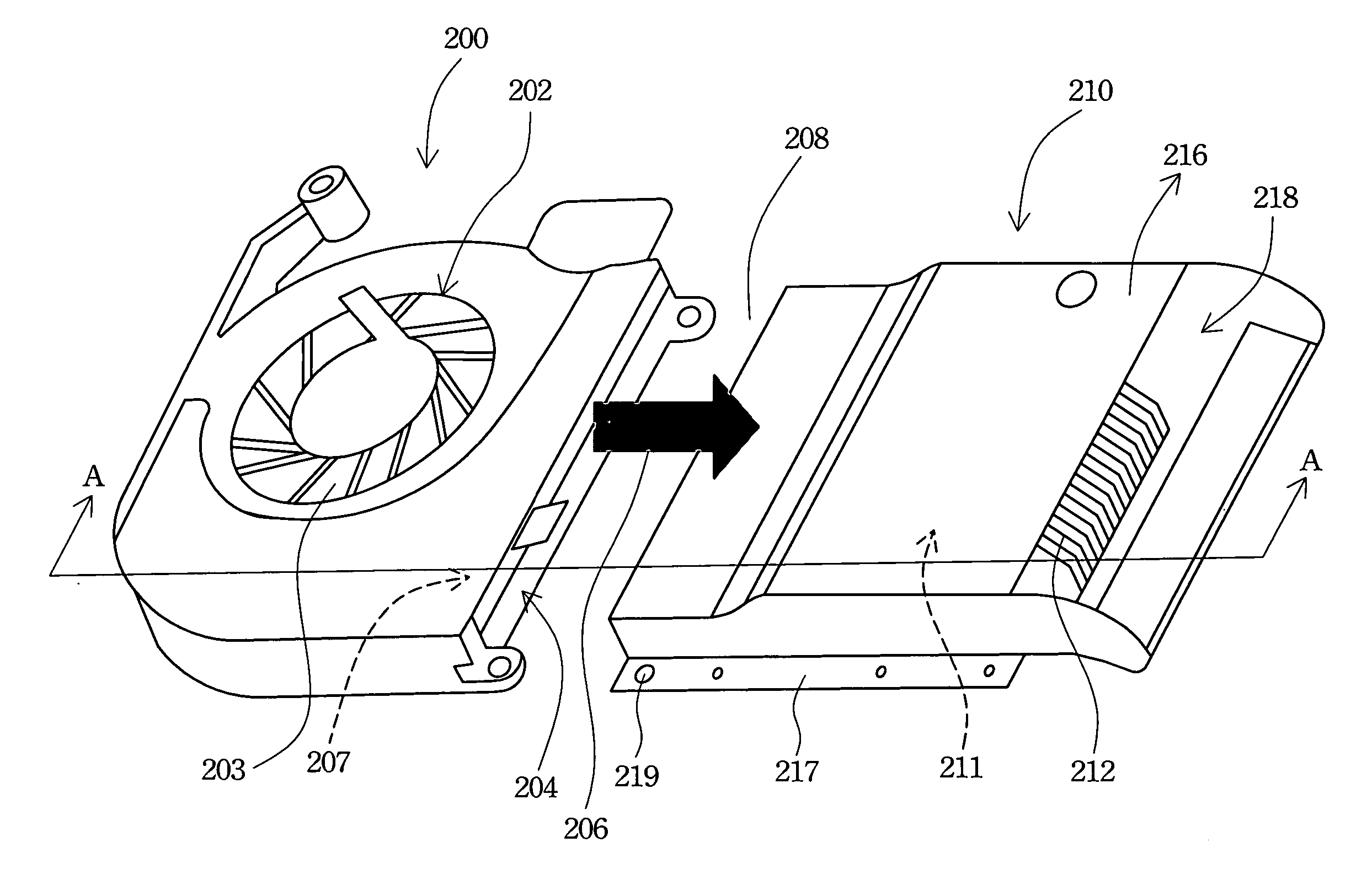
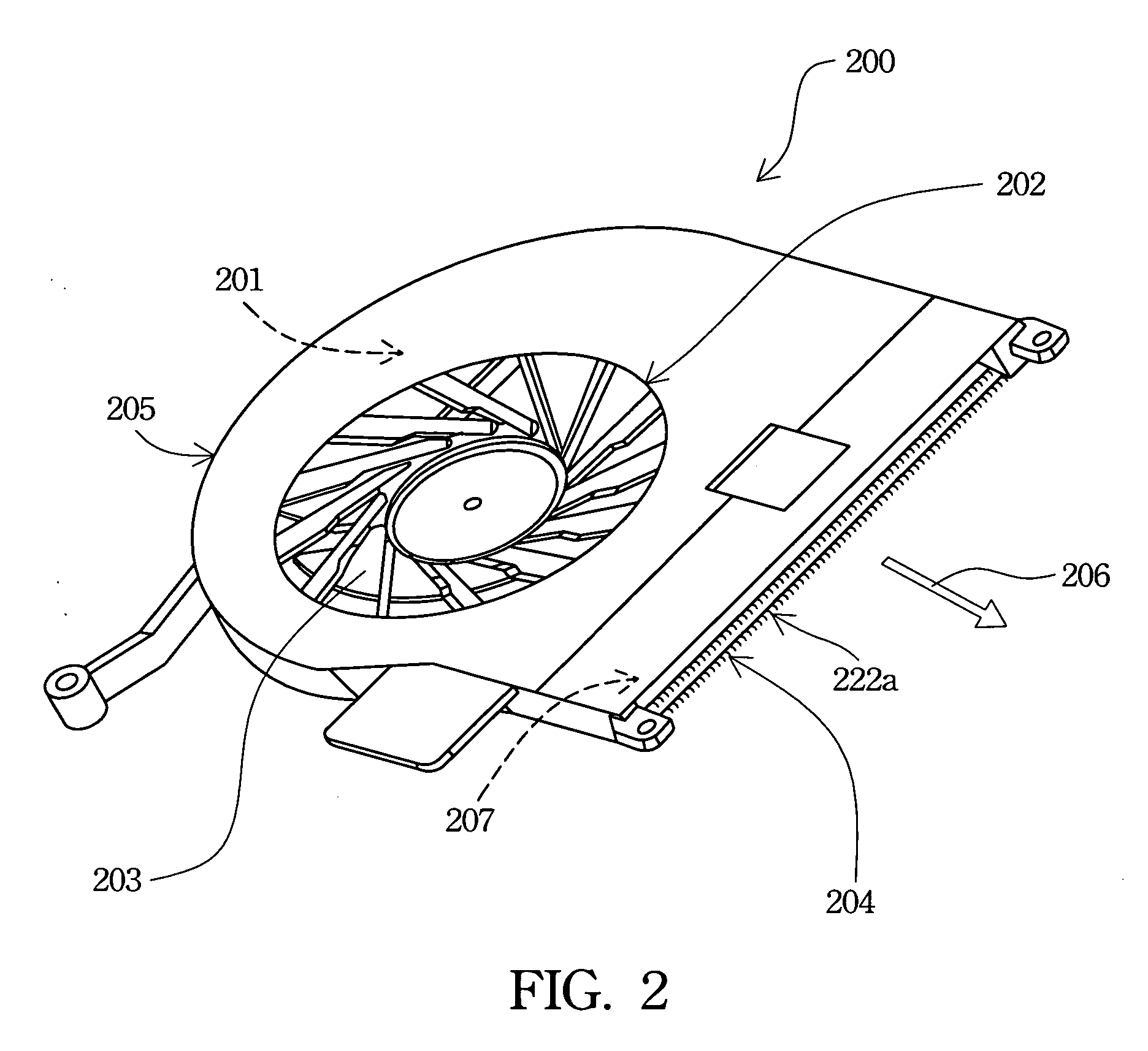
[0009] In accordance with the foregoing and other objectives of the present invention, a dissipation device includes a dissipation fin set and a centrifugal fan. The centrifugal fan outputs airflow toward the dissipation fin set to remove the heat from it. The centrifugal fan includes a centrifugal impeller mounted on a motor. An outer housing houses the motor and the centrifugal impeller. An inner wall of the housing's outlet has a hair structure to reduce noise. The dissipation fin set includes a fin structure closely attached to a heat source, as well as an airflow channel housing. The airflow channel also includes a hair structure for reducing noise.
[0010] Thus, the dissipation module with noise reduction not only decreases noise amplitudes, but also stabilizes the wake flow. Namely, the airflow with widespread Haystack noise will make a listener feel more comfortable.

Problems solved by technology

As a notebook PC becomes thinner, there isn't enough space for heat convection and heat dissipation design inside the case housing of the notebook PC.
When it comes to high-frequency components, such as the CPU (central processing unit) and graphics processing chip, the heat dissipation design hits a bottleneck.
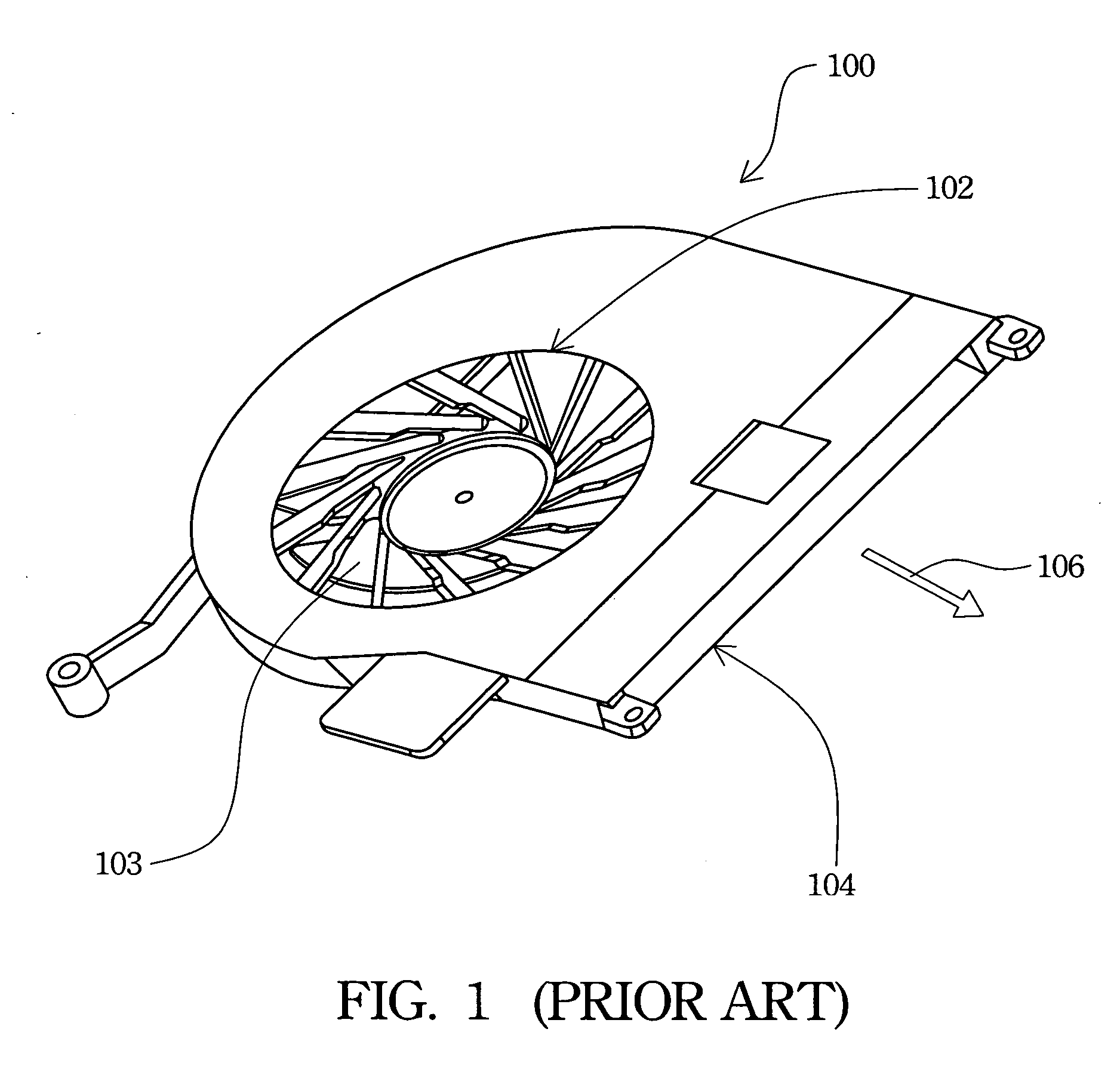
On the other hand, air driven by the centrifugal impeller 103 flows through the spiral-shaped flow channel and generates a wake flow and a vortex, which create high-frequency and narrow-band noise.
Thus, a notebook PC manufacturer faces a challenge between noise and heat dissipation efficiency.

Method used


Image

  • Heat dissipation module with noise reduction
  • Heat dissipation module with noise reduction
  • Heat dissipation module with noise reduction

Examples


Embodiment Construction

[0017] Reference will now be made in detail to the present preferred embodiments of the invention, examples of which are illustrated in the accompanying drawings. Wherever possible, the same reference numbers are used in the drawings and the description to refer to the same or like parts.

[0018] In order to reduce noise caused by strong airflow, the present invention discloses a heat dissipation module with a noise reduction function. By attaching a hair structure to an inner sidewall of a centrifugal fan's outlet, noise can be reduced. The hair structure can also be attached on an inner sidewall of a flow channel, such as a dissipation fin set, to reduce noise.

[0019]FIG. 2 illustrates a perspective view of a centrifugal fan with a noise reduction function according to one preferred embodiment of this invention. A centrifugal fan 200 includes a centrifugal impeller 203. A motor (not illustrated in FIG. 2) in the centrifugal fan 200 rotates the centrifugal impeller 203 to input air ...


PUM


Abstract

A dissipation device has a dissipation fin set and a centrifugal fan. The centrifugal fan outputs airflow toward the dissipation fin set to remove the heat from it. The centrifugal fan includes a centrifugal impeller mounted on a motor. An outer housing houses the motor and the centrifugal impeller. An inner wall of the housing's outlet has hair structure to reduce noise. The dissipation fin set includes a fin structure closely attached to a heat source, as well as an airflow channel housing. The airflow channel also includes a hair structure for reducing noise.

Description

RELATED APPLICATIONS [0001] The present application is based on, and claims priority from, Taiwan Application Serial Number 93115561, filed May 31, 2004, the disclosure of which is hereby incorporated by reference herein in its entirety. BACKGROUND [0002] 1. Field of Invention [0003] The present invention relates to a heat dissipation module. More particularly, the present invention relates to a heat dissipation module with a noise reduction function. [0004] 2. Description of Related Art [0005] As a notebook PC becomes thinner, there isn't enough space for heat convection and heat dissipation design inside the case housing of the notebook PC. When it comes to high-frequency components, such as the CPU (central processing unit) and graphics processing chip, the heat dissipation design hits a bottleneck. Thus, the mainstream framework of heat dissipation design is forced heat convection caused by a centrifugal fan. [0006]FIG. 1 illustrates a perspective view of a conventional centrifu...

Claims


Application Information

Patent Timeline
IPC IPC(8): F28F7/00H01L23/467H05K7/20
CPCH01L23/467H01L2924/3011H05K7/20172H01L2924/0002H01L2924/00F04D29/667
Inventor KAO, PING-SHENGHUANG, YU-NIENCHIEN, TSAN-NANLIU, YU
Owner QUANTA COMPUTER INC
Learn More