Control apparatus of hybrid vehicle

a control apparatus and hybrid vehicle technology, applied in battery/fuel cell control arrangement, electric devices, battery/cell propulsion, etc., can solve the problems of unsatisfactory overdischarge state of high-voltage batteries, unsatisfactory comfort for drivers, and impaired hybrid vehicle motivation power performance, etc., to achieve the effect of lowering raising the target drive torque, and improving the motive power performan

Inactive Publication Date: 2005-12-01
SUBARU CORP
View PDF17 Cites 34 Cited by
  • Summary
  • Abstract
  • Description
  • Claims
  • Application Information

AI Technical Summary

Benefits of technology

[0013] According to the invention, the high charge time torque corresponding to the high state of charge of the battery and the low charge time torque corresponding to the low state of charge of the battery are set, and the target drive torque is set to be close to the high charge time torque or the low charge time torque according to the state of charge. Therefore, when the state of charge rises, the target drive torque is raised and the motive power performance can be improved, and when the state of charge lowers, the target drive torque is lowered and the consumed electric power can be suppressed.
[0014] Besides, the high charge time torque and the low charge time torque are set, so that the torque characteristic of the target drive torque can be changed. By this, the high charge time torque can be set to the torque characteristic in which importance is given to the motive power performance, and the low charge time torque can be set to the torque characteristic in which importance is given to the suppression of consumed electric power, and the vehicle quality can be improved.
[0015] Further, since the target drive torque is set based on the accelerator operation amount, even in the case where the target drive torque is limited with the lowering of the state of charge, the target drive torque can be increased / decreased based on the accelerator operation amount. That is, even in the case where the target drive torque is limited, since the vehicle can be accelerated / decelerated according to the accelerator operation of the driver, the consumed electric power can be suppressed without giving an uncomfortable feeling to the driver.

Problems solved by technology

As stated above, the motive power performance of the vehicle is kept by the electric power from the high voltage battery, and in the case where the high voltage battery falls into an overdischarge state, the motive power performance of the hybrid vehicle is remarkably impaired.
Besides, the overdischarge state of the high voltage battery is not desirable also in view of battery deterioration.
However, when the motor output is simply limited according to the state of charge, an uncomfortable feeling is given to a driver.
For example, in the case where the motor output is limited in the depressing process of an accelerator pedal, even if the accelerator pedal is further depressed to the fully open state, the motor output is not changed to the increasing side, and there occurs a large gap between the driver's intention of accelerating and actual vehicle acceleration.
Besides, when an insufficiency of the motor output is supplemented by the engine output in order to remove the uncomfortable feeling given to the driver, the driving region of the engine goes out of the high efficient region, and the fuel consumption performance deteriorates and the purifying performance of exhaust gas deteriorates.

Method used


Image

  • Control apparatus of hybrid vehicle
  • Control apparatus of hybrid vehicle
  • Control apparatus of hybrid vehicle

Examples


Embodiment Construction

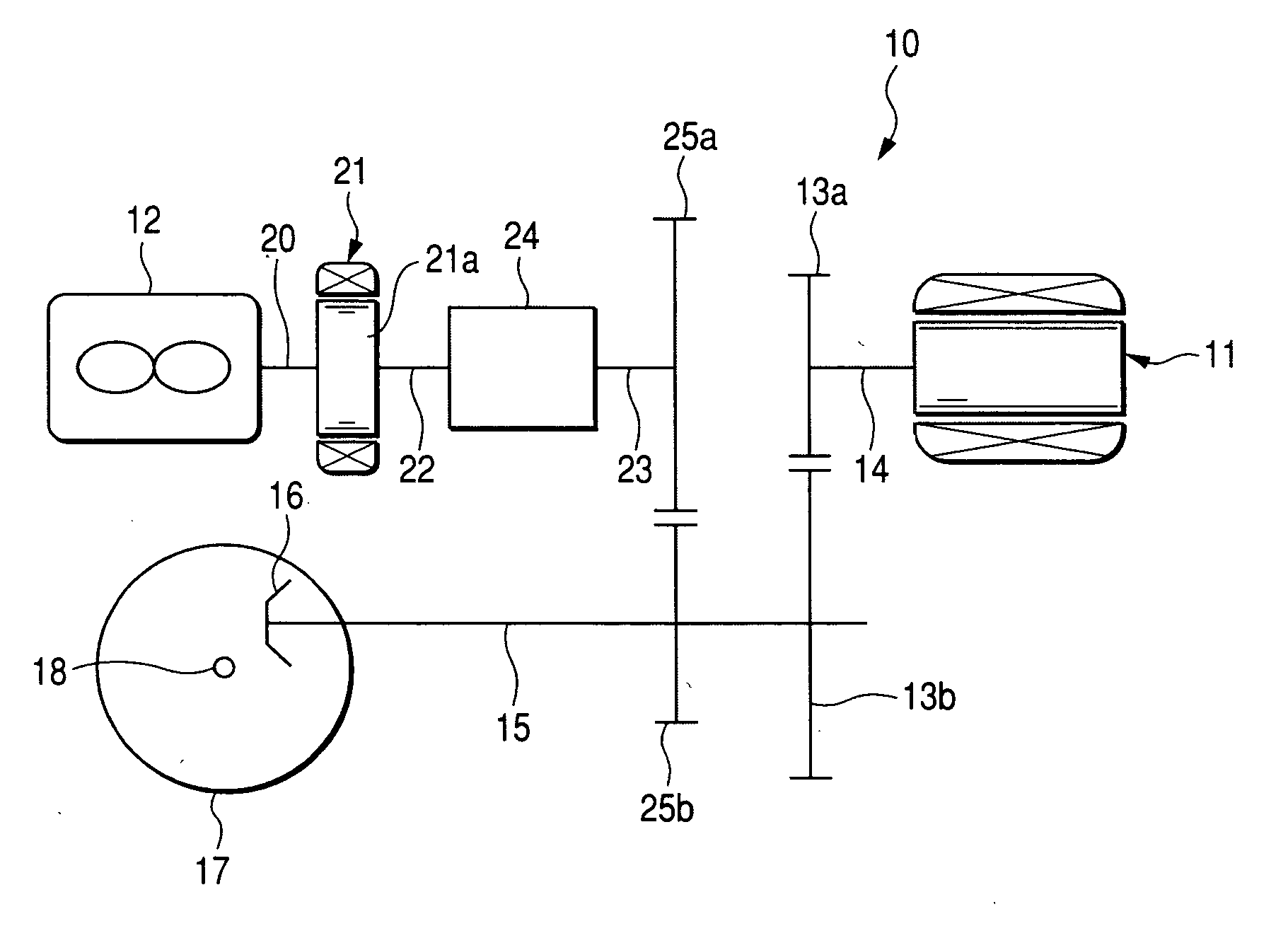
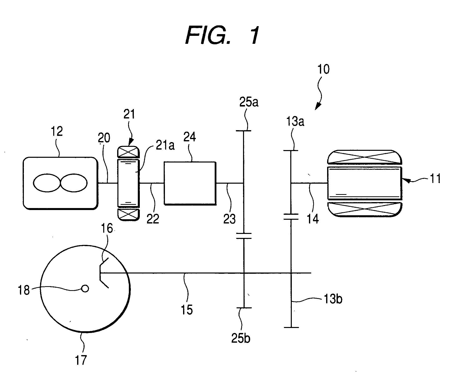
[0034] Hereinafter, embodiments of the invention will be described in detail with reference to the drawings. FIG. 1 is a schematic view showing a drive unit 10 which is controlled by a control apparatus of an embodiment of the invention. The drive unit 10 shown in FIG. 1 is the drive unit 10 applied to a front wheel drive hybrid vehicle, and includes, as power sources, a drive motor 11 as an electric motor and an engine 12 as an internal combustion engine. The drive motor 11 includes a motor output shaft 14 to which a motor side drive gear 13a is fixed, and a motor side driven gear 13b engaging with the motor side drive gear 13a is fixed to a front wheel drive shaft 15 parallel to the output shaft. Besides, a small final reduction gear 16 is fixed to a tip of the front drive shaft 15, and a not-shown differential mechanism is fitted to a large final reduction gear 17 engaging with the small final reduction gear 16. A vehicle shaft 18 extending from this differential mechanism in a v...


PUM


Abstract

Motor output is suppressed without giving an uncomfortable feeling to a driver. When a target drive torque for driving a wheel is set, a high charge time torque which can be outputted in a high state of charge of a battery and a low charge time torque which can be outputted in a low state of charge of the battery are set based on an accelerator operation amount and a vehicle speed. Subsequently, a difference between the high charge time torque and the low charge time torque is multiplied by a charge correction coefficient corresponding to a state of charge, this calculated value is added to the low charge time torque Tl, and the target drive torque is calculated. Accordingly, the target drive torque can be lowered according to the state of charge, and overdischarge of the battery can be prevented. Further, even in the case where the target drive torque is lowered, the target drive torque can be changed according to the accelerator operation, and an excellent feeling can be given to the driver.

Description

CROSS REFERENCE TO RELATED APPLICATIONS [0001] The disclosure of Japanese Application No. 2004-163284 filed on Jun. 1, 2004 including the specification, drawing and abstract is incorporated herein by reference in its entirety. BACKGROUND OF THE INVENTION [0002] 1. Field of the Invention [0003] The present invention relates to a control apparatus of a hybrid vehicle in which a driving wheel is driven by using at least one of an engine and an electric motor. [0004] 2. Description of the Related Art [0005] In recent years, a hybrid vehicle in which an engine and an electric motor are mounted as power sources has been developed. In this hybrid vehicle, the electric motor is used as the power source at the time of start and at the time of low speed, so that the driving region of the engine can be restricted within a high efficient region, and accordingly, the engine efficiency is improved and low fuel consumption can be achieved. As drive systems of such hybrid vehicles, there have been ...

Claims


Application Information

Patent Timeline
Patent Type & Authority Applications(United States)
IPC IPC(8): B60W20/00B60K6/442B60L3/00B60L50/16B60W10/06B60W10/08B60W10/26
CPCB60K6/48Y02T10/6221B60W10/26B60K6/442B60L3/0046B60L15/20B60L2240/12B60L2240/14B60L2240/421B60L2240/423B60L2240/545B60L2240/547B60L2240/549B60L2250/26B60W10/02B60W10/06B60W10/08B60W2510/244B60W20/13B60L50/16B60L50/61B60L58/13B60L58/14B60L58/15Y02T10/62Y02T10/64Y02T10/70Y02T10/7072Y02T10/72
Inventor FUJIKI, HARUO
Owner SUBARU CORP
Why Eureka
Try Eureka