Method of high selectivity SAC etching

a sac etching and high selectivity technology, applied in the direction of electrical equipment, decorative surface effects, decorative arts, etc., can solve the problems of etching stop phenomenon, inability to keep corner selectivity, and inability to complete etching, etc., to achieve high selectivity, large process window, and high etching rate

Inactive Publication Date: 2005-12-01
TOKYO ELECTRON LTD
View PDF16 Cites 7 Cited by
  • Summary
  • Abstract
  • Description
  • Claims
  • Application Information

AI Technical Summary

Benefits of technology

[0011] Accordingly, one object of the present invention is to provide a method for SAC etching that provides high SiO / SiN selectivity while avoiding etch stop.
[0012] A further object of the present invention is to provide a method for SAC etching that provides high etch rate and high selectivity within a large process window.
[0013] A further object of the present invention is to provide a method for SAC etching that can be performed while simultaneously providing island contact etching with high verticality of the island contact walls.

Problems solved by technology

Unfortunately, high selectivity SAC etching with these gases is also accompanied by the etch stop phenomenon, where the etching is incomplete, stopping in the middle of the hole due to fast polymerization, particularly in narrow slits between the gate electrodes.
Thus it is becoming ever more difficult to keep the corner selectivity without encountering etch stop in the slit.
It is also known that there is usually observed a lower selective portion on the small overlapped nitride corner and at the worst case, this phenomenon causes an electrical short problem.
The etch stop phenomenon is particularly a problem when the etching parameters must be controlled in a narrow process window.
On the other hand, the superior and strong carbon rich polymerization often cases various other problems such as an etching profile micro loading between dense and isolated patterns, a slow etching rate, low throughput and short mean time between wet cleanings (MTBWC).
Conventionally, it has been essential to separate island contact etching on a peripheral area or gate contact etching processes from SAC etching because it is very difficult to get a vertical profile and maintain enough good contact resistance when etched at the same time or with the same process due to superior and strong carbon rich polymerization.
Unfortunately, the conventional use suffers from a low etching rate and tends to leave the corners from the etching process too sharp.
Unfortunately, these two procedures tend to cause etch stopping, described above.

Method used


Image

  • Method of high selectivity SAC etching
  • Method of high selectivity SAC etching
  • Method of high selectivity SAC etching

Examples


example

Example 1

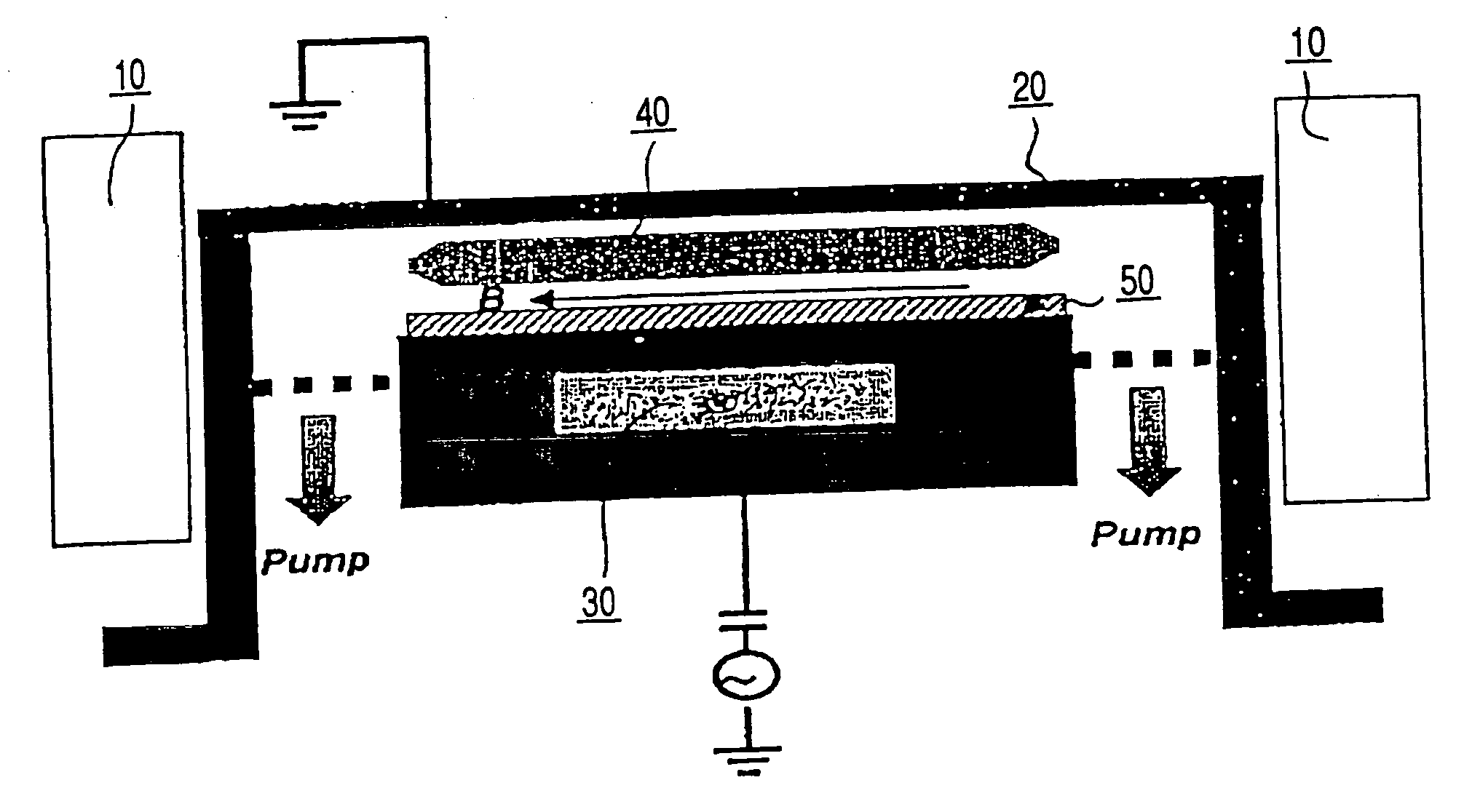
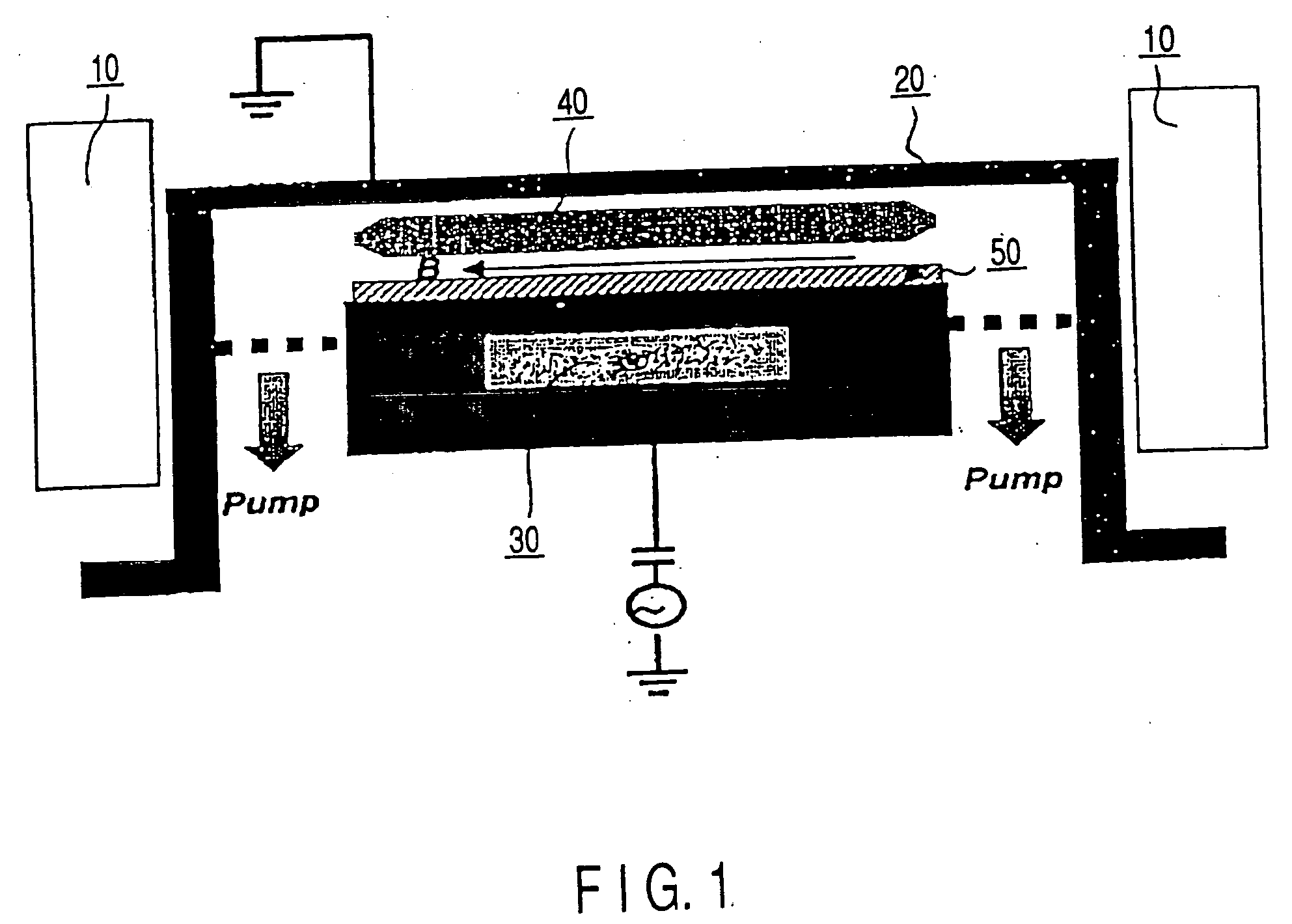
[0050] As a typical example of this invention, one of the etching recipes is described in the following for a high etch rate SAC etching process, with vertical island Contact etching at the same time.

Etching Recipe (1):Descum Etch:40 mT 1400 WCF4 / Ar / O2 = 80 / 160 / 20 sccm, 7 secILD Etch-1:30 mT 1700 WC4F8 / CO / Ar / O2 = 25 / 50 / 250 / 10 sccm,60 / 60° C. (note in this and the followingexamples, this represents temp of topelectrode and wall / temp of cathode)Back He C / E = 7 / 30 T, 45 secILD Etch-2:60 mT 1700 W C4F8 / CO / Ar / O2 = 20 / 00 / 500 / 10 sccm,60 / 60° C. Back He C / E = 7 / 30 T, 75 secNitride Etch:50 mT 800 W CHF3 / Ar / O2 = 10 / 100 / 20 sccm,Process Gap = 37 mm,Back He C / E = 7 / 40 T, 9 sec

[0051] The etch rate of ILD-Etch.1 (1st stage etching) was approximately 1.5 times faster than conventional SAC etching.

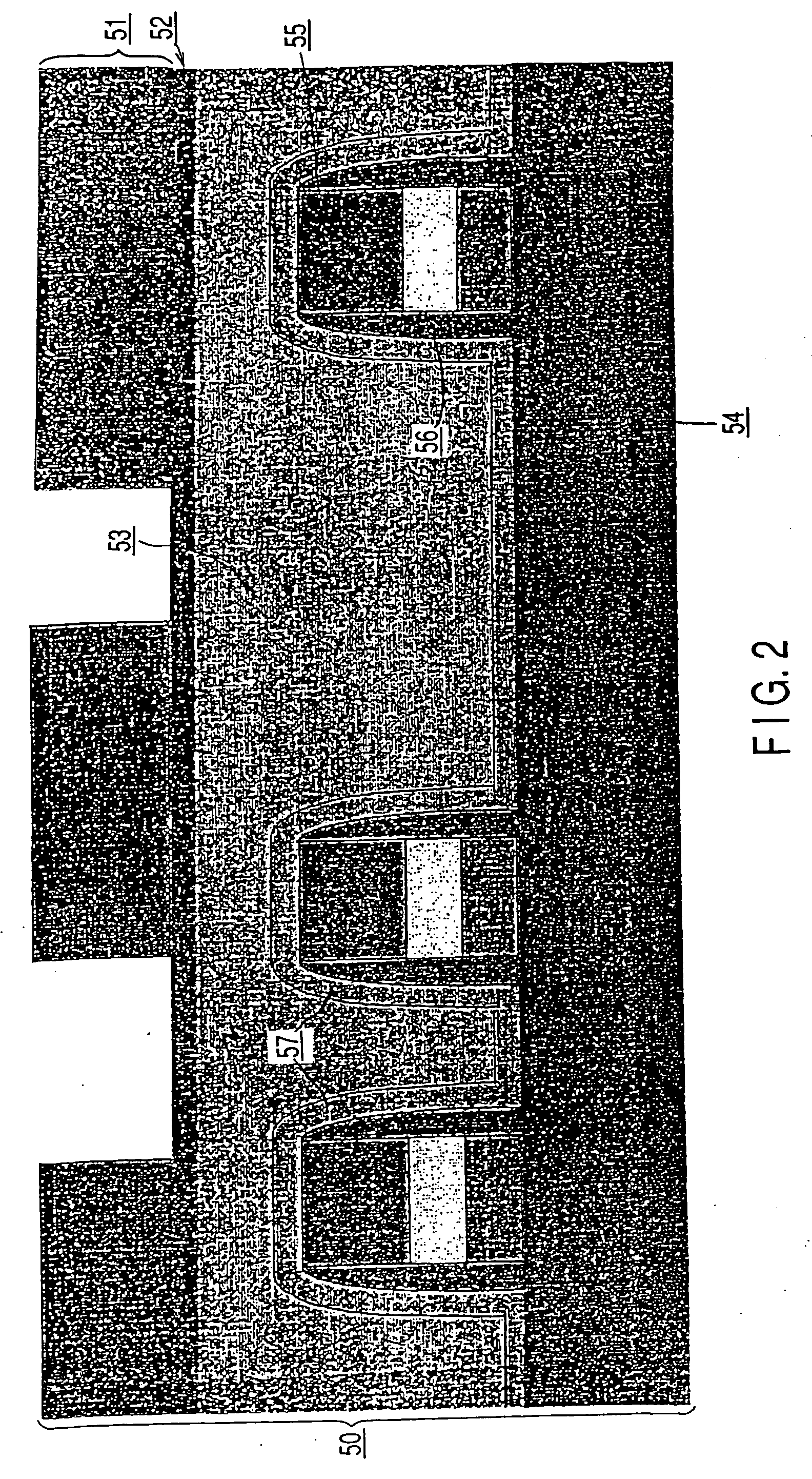
[0052] Moreover, combined with ILD-Etch.2 (2nd stage etching), the corner etching profile had a smooth and rounded shape. The shortest distance with etching recipe (1) between the corners of the...

example 2

[0059] Highly selective SAC etching technique with the vertical island Contact etching at the same time

Etching Recipe (2):Descum Etch:40 mT 1400 W CF4 / Ar / O2 = 80 / 160 / 20 sccm,7 secILD Etch-1:50 mT 1700 W C5F8 / CO / Ar / O2 =10 / 150 / 480 / 6 sccm, 60 / 60° C.,Back He C / E = 7 / 40 T, 122 secI LD Etch-2:50 mT 1500 WC5F8 / CO / Ar / O2 = 6 / 00 / 500 / 6 sccm, 60 / 60° C.Back He C / E = 7 / 40 T, 70 secNitride Etch:50 mT 800 W CHF3 / Ar / O2 = 10 / 100 / 20 sccm,60 / 60° C., Back He C / E = 7 / 40 T, 9 sec,Process Gap = 37 mm

[0060] Etching Recipe (2) includes C5F8 chemistries, which is more selective to SiN than C4F8, due to the higher C / F atomic-ratio, and could generate more carbon rich polymerization. However etching recipe (2) described above achieved vertical contact profile all over the wafer with greater than 87° walls at the 0.27 μm hole size.

[0061] Conventional highly selective SAC etching with C5F8 chemistries give slightly tapered profiles with around 82-84° at the 0.27 μm hole size. So the contact resistance would be...

example 3

[0067] Highly selective and high etch rate SAC etching technique with the vertical island Contact etching at the same time

Etching Recipe (3):Descum Etch:40 mT 1400 W CF4 / Ar / O2 = 80 / 160 / 20 sccm,7 secILD Etch-1:30 mT 1700 WC4F8 / CO / Ar / O2 = 25 / 50 / 250 / 10 sccm,60 / 60° C.,Back He C / E = 7 / 30 T, 45 secILD Etch-2:50 mT 1500 W C5F8 / CO / Ar / O2 = 10 / 00 / 500 / 10 sccm, 60 / 60° C.Back He C / E = 7 / 30 T, 90 secNitride Etch:50 mT 800 W CHF3 / Ar / O2 = 10 / 100 / 20 sccm,Process Gap = 37 mm,Back He C / E = 7 / 40 T, 9 sec

[0068] This example combined the benefits of C4F8 chemistry in Example 1 with the benefits of C5H8 chemistry in Example 2 and gave highly selective and high etch rate SAC etching with the vertical island Contact etching at the same time.

[0069] So Etching recipe (3) would be one example of the ultimate SAC etching technique to have a total solution for current ULSI fabrication.

[0070] Further etching recipes are provided below. These recipes could maintain about 700 from the corner of the poly gate, w...


PUM

PropertyMeasurementUnit
pressureaaaaaaaaaa
pressureaaaaaaaaaa
temperatureaaaaaaaaaa

Abstract

A method for SAC etching is provided involving a) etching a Si wafer having a nitride present thereon with a first etching gas containing a first perfluorocarbon and carbon monoxide, and b) etching the resultant Si wafer having an initially etched nitride photoresist thereon with a second etching gas containing a second perfluorocarbon in the substantial absence of carbon monoxide, wherein the etching steps a) and b) are performed at high RF power and low pressure compared to conventional processes to provide higher selectivity etching and a larger process window for SAC etching, as well as the ability to perform SAC etching and island contact etching under the same conditions with high verticality of the island contact and SAC walls.

Description

TECHNICAL FIELD [0001] The present invention provides a method for providing high selectivity in self-aligned contact (SAC) etching by use of a high ion energy plasma generated with high RF power at low process pressure. BACKGROUND ART [0002] Self-aligned Contact (SAC) is one of the key technologies in ULSI (Ultra Large Scale Integration) fabrication. SAC can relax the alignment margin in photolithography. The selectivity to SiN at the corner (shoulder) is the most important issue in SAC etching. [0003] Therefore, over the years of process development in SAC etching, heavy polymerization chemistries have been relied on in order to get high selectivity to nitride (i.e. ratio of [oxide etch rate] / [nitride etch rate]), because the nitride corner is exposed to plasma for a longer time or a longer over-etching than the bottom nitride. For achieving high corner selectivity, gases having high C / F atomic ratio, such as C4F8, are used in SAC etching. Additionally, CH3F or CH2F2 addition is r...

Claims


Application Information

Patent Timeline
Patent Type & Authority Applications(United States)
IPC IPC(8): H01L21/3065H01L21/311H01L21/60
CPCH01L21/76897H01L21/31116H01L21/28
Inventor TSUCHIYA, KAZUO
Owner TOKYO ELECTRON LTD
Why Eureka
Try Eureka