Apparatus and method for melt spinning dyed yarn filaments

a dyed yarn and filament technology, applied in the field of apparatus for spinning dyed filaments, can solve the problems of dye irregularities in the spun filaments, short reaction time, long downtime, etc., and achieve the effects of high coloration flexibility, polymer melt, and great flexibility

Inactive Publication Date: 2005-12-01
SAURER GMBH & CO KG
View PDF2 Cites 48 Cited by
  • Summary
  • Abstract
  • Description
  • Claims
  • Application Information

AI Technical Summary

Benefits of technology

[0008] A further advantage of the invention lies in that the location of the dye addition between the melt producer and the spinneret is freely selectable, so that a great flexibility results in the production of dyed filaments. Thus, the invention can be used for spinning single color yarns, multicolored yarns, or colored staple filaments, as well as spunbonds.
[0009] As a function of the used base polymer, with all spinnable and dyeable base polymers being basically suited, it is possible to carry out the mixing steps in certain, predetermined sequences. To this end, the static mixer may be arranged within the mixer combination in the direction of the flow either upstream or downstream of the dynamic mixer.
[0010] It is likewise possible to use besides the dynamic mixer, a plurality of static mixers alternately or serially connected. However, it is also possible to provide besides one or more static mixers a plurality of dynamic mixers.
[0011] To spin single color filaments, it is preferred to use the further development of the invention, wherein the polymer melt is dyed after having been produced and before being divided into a plurality of partial melt flows. In this case, the mixing unit and the dye metering device are arranged in the flow direction upstream o

Problems solved by technology

However, the known apparatus have in general the disadvantage that when a dye is changed, it will be necessary to flush the apparatus completely from the melt producer right to the individual spinnerets, so that long downtimes result.
In particular, when liquid

Method used


Image

  • Apparatus and method for melt spinning dyed yarn filaments
  • Apparatus and method for melt spinning dyed yarn filaments
  • Apparatus and method for melt spinning dyed yarn filaments

Examples


Embodiment Construction

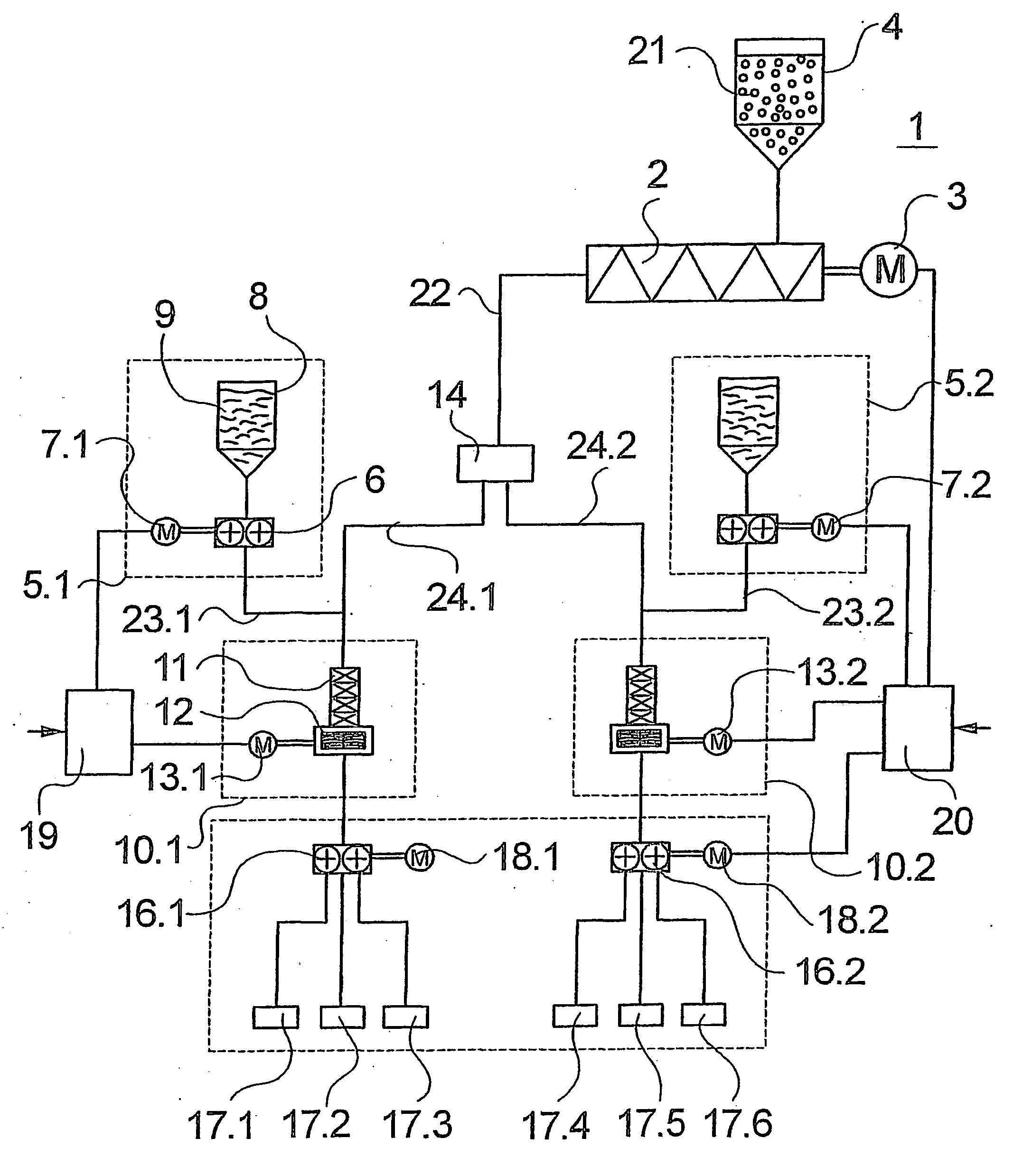
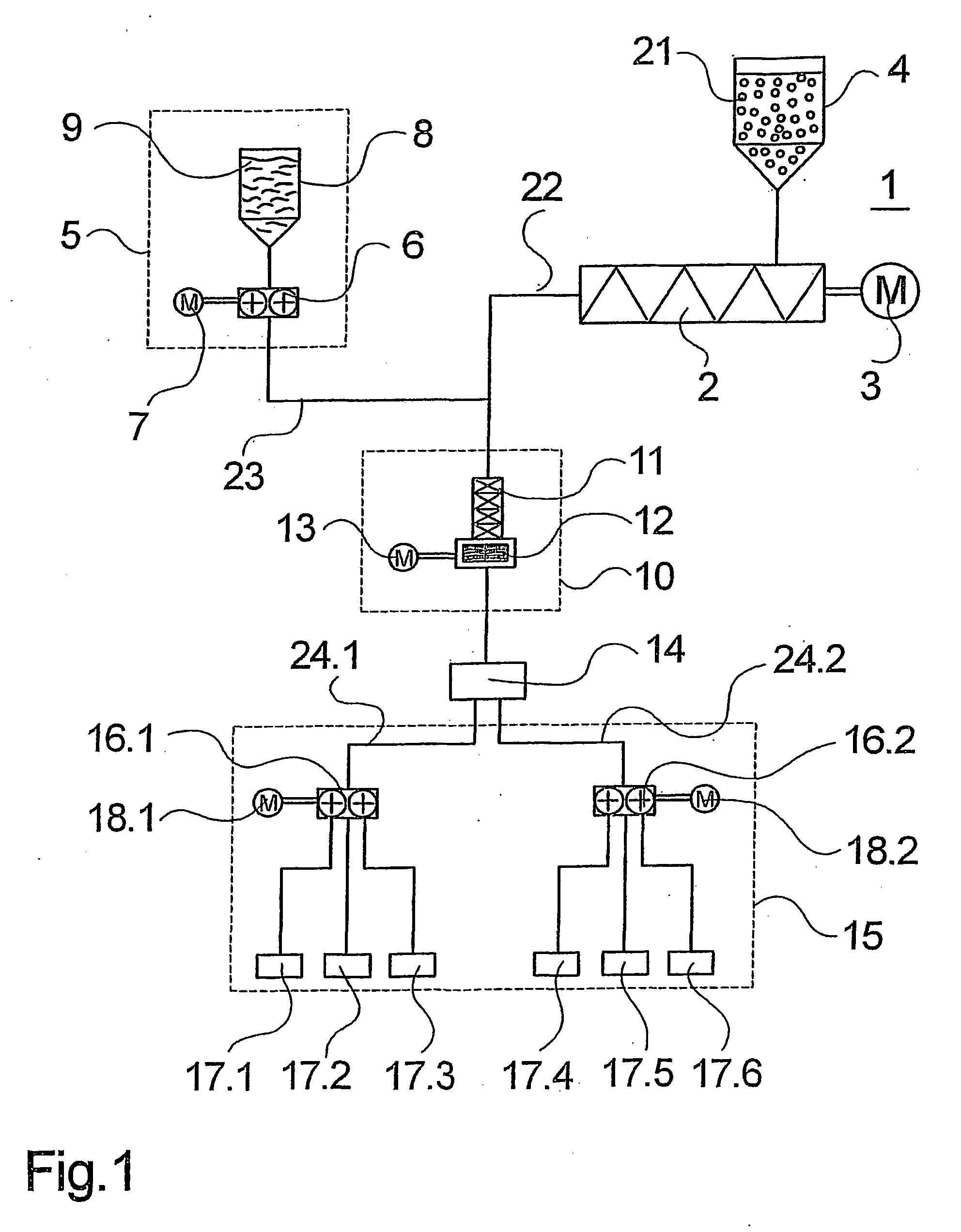
[0020]FIG. 1 illustrates a first embodiment of an apparatus according to the invention for spinning single color filaments to produce from the filaments, for example, crimped carpet yarns. To this end, the apparatus comprises a melt producer 1. The melt producer 1 is shown as an extruder with an extruder screw 2 and an extruder drive 3. The melt producer 1 includes a feed hopper 4 for receiving granules 21. The melt producer 1 connects to a melt line 22.

[0021] Into the melt line 22, a feed line 23 extends, which connects to a dye metering device 5. The dye metering device 5 comprises a metering pump 6 and a tank 8 connecting to the metering pump 6. The metering pump 6 is driven via a drive 7. The tank 8 holds a liquid dye 9. In the direction of the flow, downstream of the inlet of feed line 23, a mixing unit 10 connects to the melt line 22. The mixing unit 10 comprises a static mixer 11 and a dynamic mixer 12 that is driven by a drive 13. The static mixer 11 and dynamic mixer 12 ar...


PUM

PropertyMeasurementUnit
Flow rateaaaaaaaaaa
Melting pointaaaaaaaaaa

Abstract

An apparatus and a method for spinning dyed filaments from a dyed polymer melt, wherein an undyed polymer melt is produced by a melt producer. A liquid dye is added to the polymer melt by means of a dye metering device. To mix the liquid dye and dye the polymer melt, a mixing unit is provided. The dyed polymer is then spun to filaments by means of a spin unit. To obtain before the spinning step a uniform coloration of the polymer melt despite the short dwelling time of the liquid dye in the polymer melt, the liquid dye and the polymer melt are mixed in a plurality of successive mixing units which are formed by a mixer combination comprising at least one static mixer and at least one dynamic mixer.

Description

CROSS REFERENCE TO RELATED APPLICATION [0001] The present application is a continuation of international application PCT / EP2004 / 000511, filed 22 Jan. 2004, and which designates the U.S. The disclosure of the referenced application is incorporated herein by reference.BACKGROUND OF THE INVENTION [0002] The invention relates to an apparatus for spinning dyed filaments from a dyed polymer melt, as well as a method for spinning dyed filaments from a dyed polymer melt. An apparatus and a method of this general type are disclosed, for example, in DE 199 56 251 A1. [0003] To be able to produce dyed filaments to e used in forming endless carpet yarns, it is necessary to dye the base polymers by adding dyes before spinning. To this end, different variants of apparatus and methods are known in the art. In a first variant, the dye is supplied together with the granules of the base polymer to a melt producer, so that melting and mixing are carried out by the melt producer in one step. Systems of...

Claims


Application Information

Patent Timeline
IPC IPC(8): D01D1/06
CPCD01D1/065B29C47/363B29C47/362B29C48/362B29C48/363B29C48/365B29B7/325B29B7/94B29B7/7466B29B7/748B29B7/603
Inventor REUTTER, TILMANHUBNER, DIETHARDZUHLKE, JORN
Owner SAURER GMBH & CO KG
Why Eureka
Try Eureka