

Electric tweezers
a technology of electric tweezers and tweezers, which is applied in the direction of micromanipulators, load-engaging elements, gripping heads, etc., can solve problems such as complicated operation, and achieve the effect of simple structur
- Summary
- Abstract
- Description
- Claims
- Application Information
AI Technical Summary
Benefits of technology
Problems solved by technology
Method used
Image

Examples
first embodiment
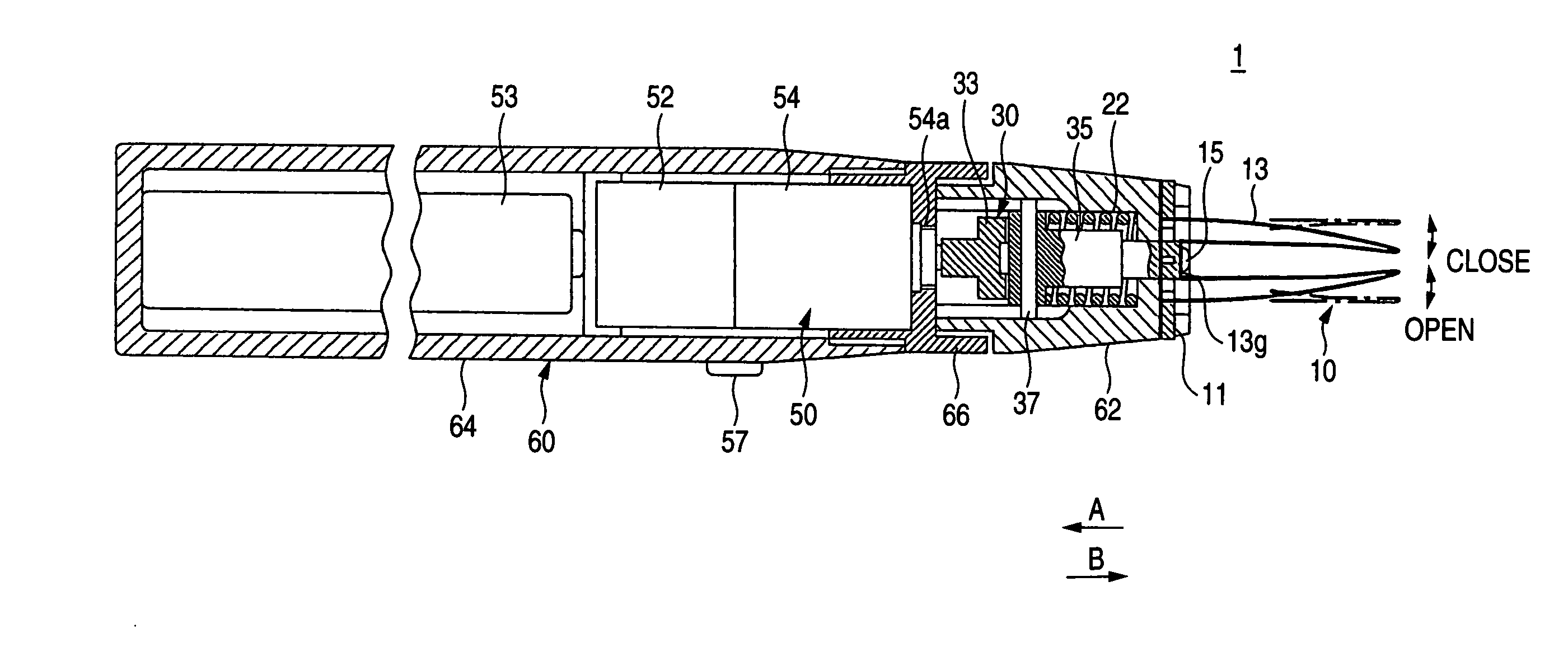
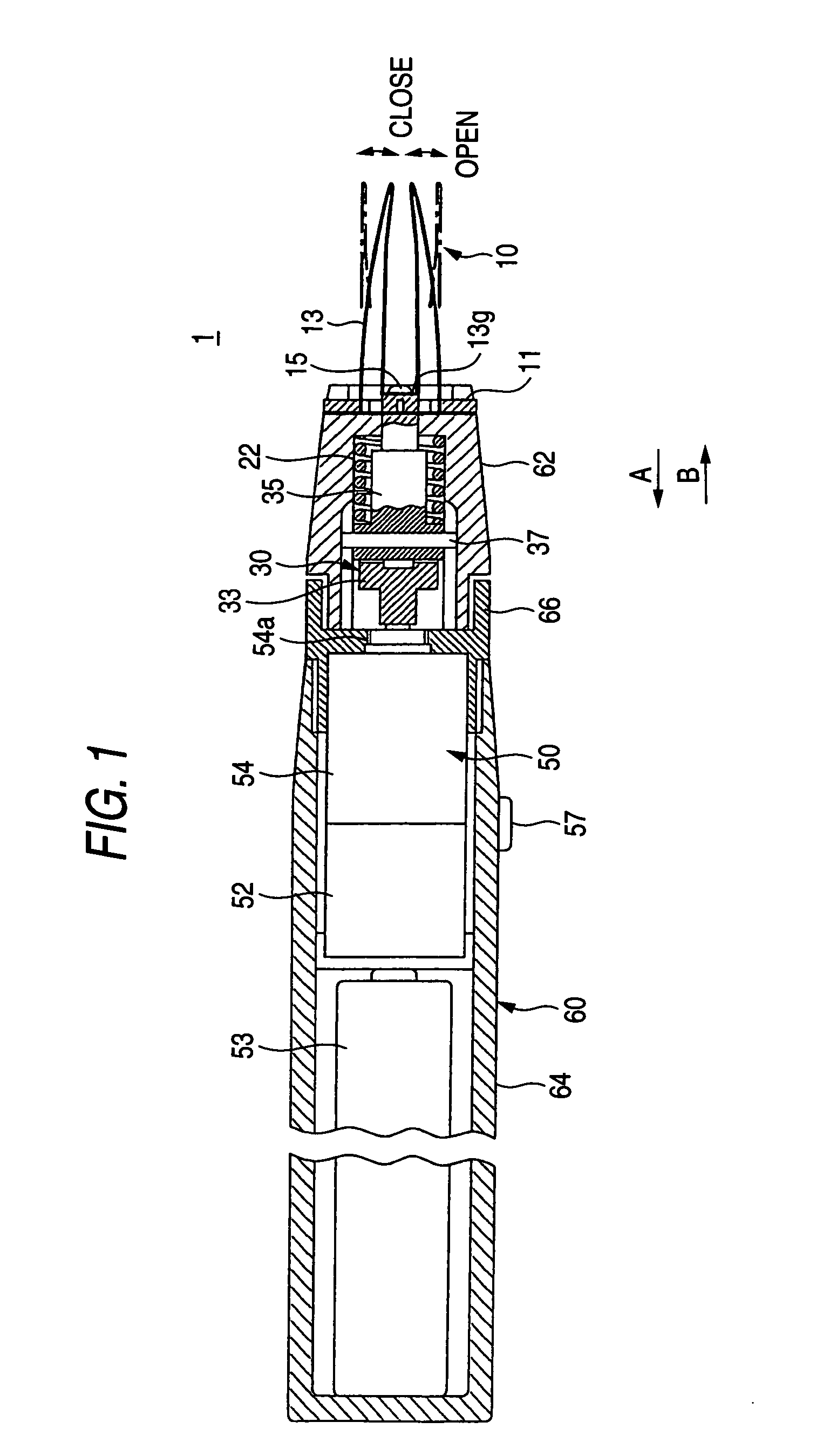
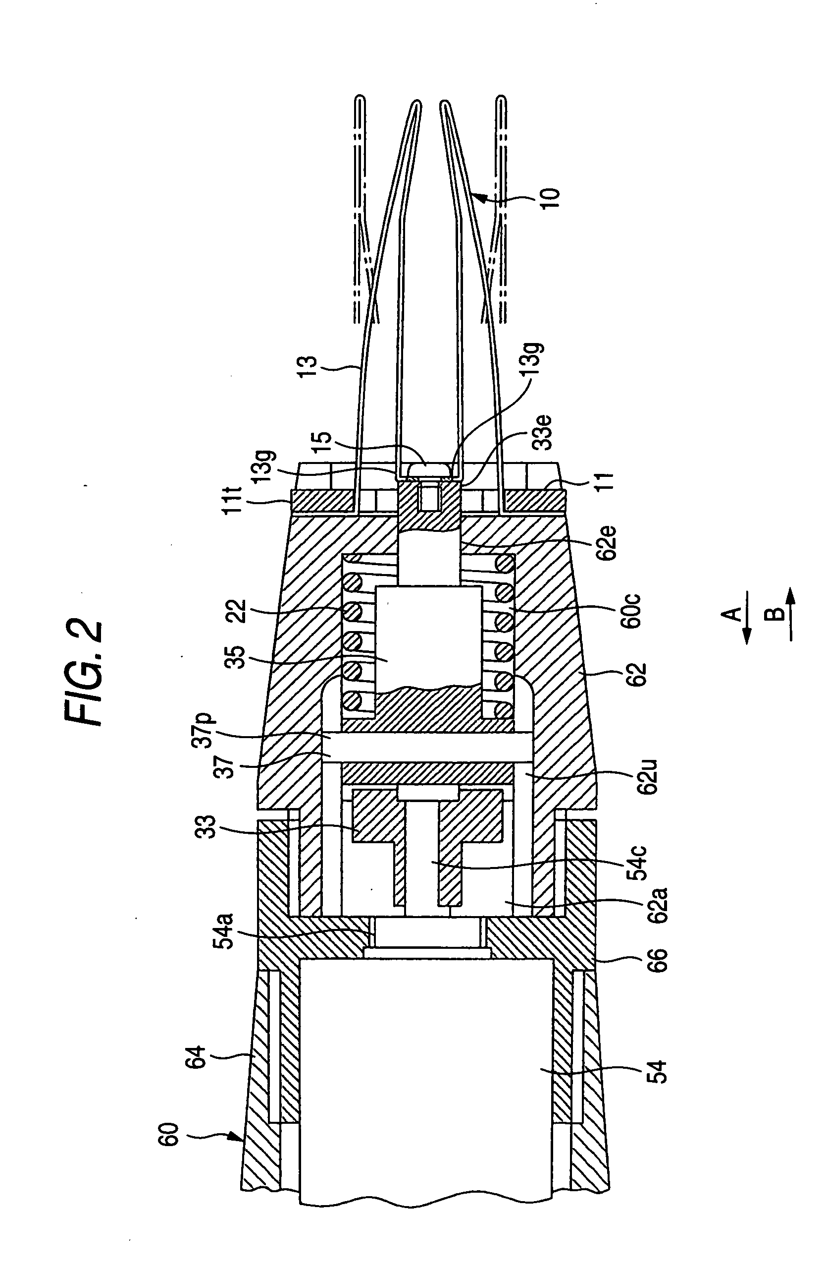
[0029] Now referring to FIGS. 1 to 5, an explanation will be given of an electric tweezers according to an embodiment of this invention. FIG. 1 is an entire cross-sectional view of electric tweezers according to an embodiment of this invention. FIG. 2 is a partial enlarged view of a main part of the electric tweezers shown in FIG. 1. FIG. 3 is a perspective view of a finger unit. FIG. 4 is an exploded perspective view of a transformation mechanism and a motor of the electric tweezers. FIG. 5 is a plan view (a) and a front sectional view (b) of a holder member.
[0030] In FIGS. 1 to 5, the electric tweezers 1 includes a gripping finger 13 which serve as a gripping member having one end portion and the other end portion, a finger unit 10, a driving section 50 having a motor 52 connected to a common portion (the other end portion) 13g for translationally displacing the common portion 13g, a transformation mechanism 30 which serves to transform the rotation in a prescribed direction whic...
second embodiment
[0061] Referring to FIGS. 7 and 8, an explanation will be given of another embodiment of this invention. FIG. 7 is a plan view of a base member. FIG. 8 is a perspective view for explaining the attachment / detachment between the base member and a holder member.
[0062] In the first embodiment, the opening / closing direction of the gripping finger 13 could be selected. In this embodiment, the selection can be made continuously.
[0063] In FIGS. 7 and 8, a base member 211 is formed in a flat washer shape. The base member 211 has a substantially circular outer periphery (outer edge) and a hole 211e formed at the center. Like the first embodiment, the base member 211 has two recesses 211c which are to be engaged with the gripping finger 13 while the one end portion thereof is nipped.
[0064] Each of slits 211s of the base member 211 is composed of a horizontal slit 211h which is horizontally recessed toward the inside of the central portion and an arc-shaped slit 211L which communicates with ...
third embodiment
[0070] Referring to FIGS. 9 and 10, an explanation will be given of still another embodiment of this invention. FIG. 9 is a plan view of a base member, and FIG. 10 is an exploded front view including a partial section of each of a finger unit, a magnet member and a holder member.
[0071] Like the second embodiment, this embodiment intends to select the opening / closing direction of the gripping finger 13 continuously, and also facilitate the attachment / detachment between a finger unit 310 (gripping finger 13) and a holder member 362.
[0072] In FIGS. 9 and 10, a base member 311 is made of a magnetic substance such as iron, and formed in a ring-shape having a hole in the center. The base member 311 has two recesses 311c which are to be engaged with the gripping finger 13 while the one end portions of the gripping finger 13 are nipped.
[0073] The holder member 362 has a shape similar to that in the second embodiment, i.e. includes a cylindrical portion 362y formed at the tip, a pair of c...
PUM
 Abstract
Description
Claims
Application Information