Parking assist control apparatus and storage medium for parking assist control program

a technology of assist control and storage media, which is applied in the direction of steering initiation, instruments, vessel construction, etc., can solve the problems of inability to automatically generate braking force, failure of automatic pressure increase system, and simple end of parking assist control

Inactive Publication Date: 2005-12-01
ADVICS CO LTD
View PDF12 Cites 46 Cited by
  • Summary
  • Abstract
  • Description
  • Claims
  • Application Information

AI Technical Summary

Benefits of technology

[0009] The present invention thus provides a parking control brake control apparatus capable of responding in a case in which an abnormality has occurred in a vehicle side device used in parking brake control when parking assist brake control is executed.

Problems solved by technology

When executing parking assist control in a parking assist brake control apparatus such as that described above, there is a possibility that an abnormality may occur in a vehicle side device such as a distance measuring sensor (such as corner sonar, laser radar, an on-board camera, or the like) used to execute the parking assist brake control, or that brake failure of an automatic pressure increase system may occur.
If such an abnormality occurs in the parking assist control apparatus of the related art, however, either no treatments are taken or the parking assist control is simply ended.
Thus, in the event of an abnormality in a distance measuring sensor, braking force is unable to be automatically generated during the parking assist control and the vehicle may no longer be able to be moved at an appropriate predetermined speed (i.e., creep speed).
Further, in the event of brake failure, there is a possibility that braking force may be unable to be automatically generated during parking assist control and the vehicle may no longer be able to be moved at the appropriate predetermined speed.
Because an abnormality of the distance measuring sensor may also occur when the vehicle is running at high speeds, however, no brake control is performed even if an abnormality occurs in a distance measuring sensor.
In this case as well, however, only an electrical abnormality check of the automatic pressure increase system is performed in the check immediately before parking assist brake control is executed; a hardware abnormality check is not performed.
Thus, it is possible that a hardware abnormality may occur during parking assist brake control.

Method used


Image

  • Parking assist control apparatus and storage medium for parking assist control program
  • Parking assist control apparatus and storage medium for parking assist control program
  • Parking assist control apparatus and storage medium for parking assist control program

Examples


first embodiment

[0036] A parking assist control apparatus mounted in a vehicle to which a first embodiment of the present invention is applied will now be described with reference to the appended drawings.

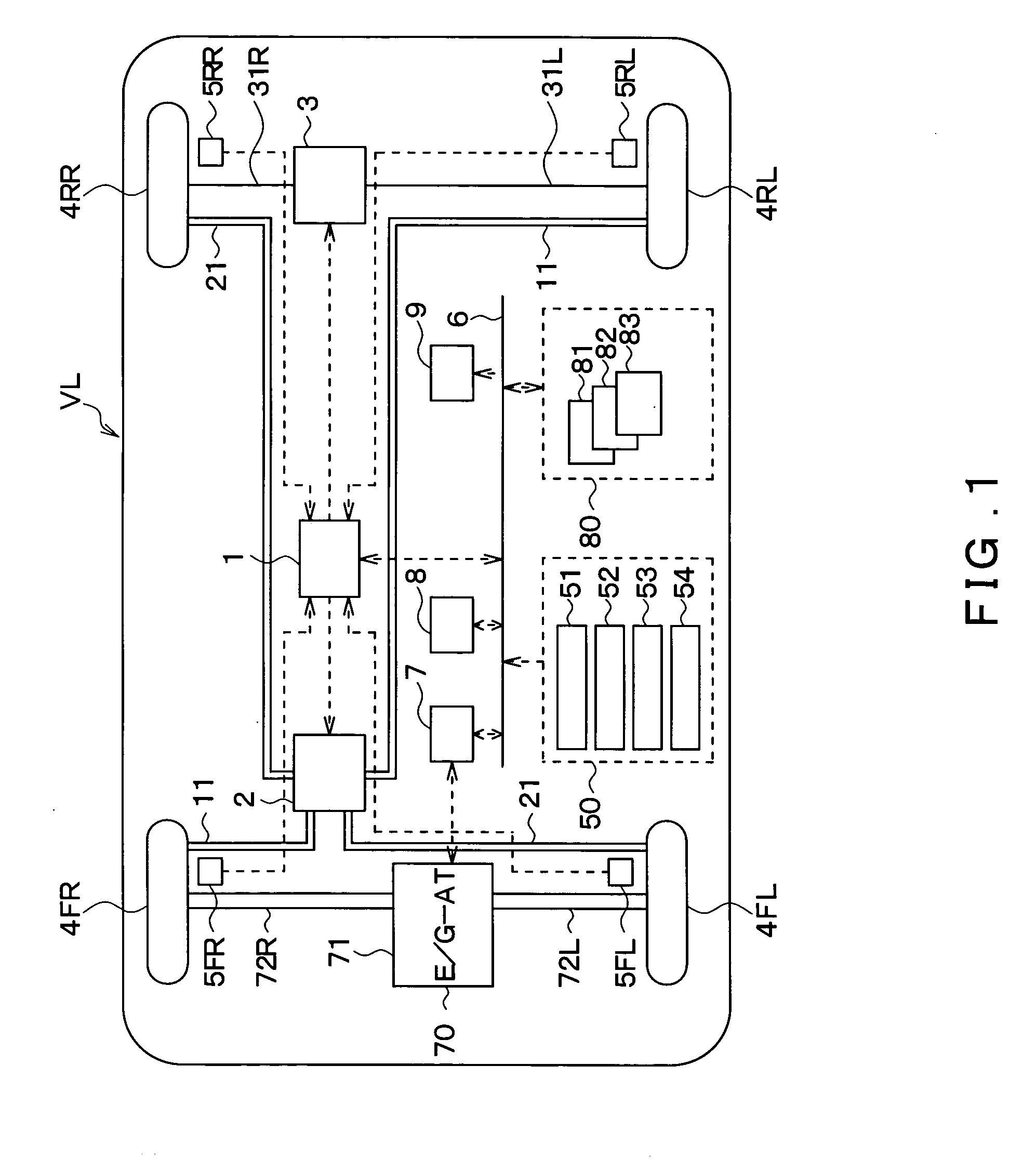
[0037]FIG. 1 is a diagram of the overall configuration of a parking assist brake apparatus according to the present embodiment. In the drawing, the structural elements corresponding to a right front wheel, a left front wheel, a right rear wheel, and a left rear wheel of a vehicle VL are denoted by reference characters FR, FL, RR, and RL, respectively.

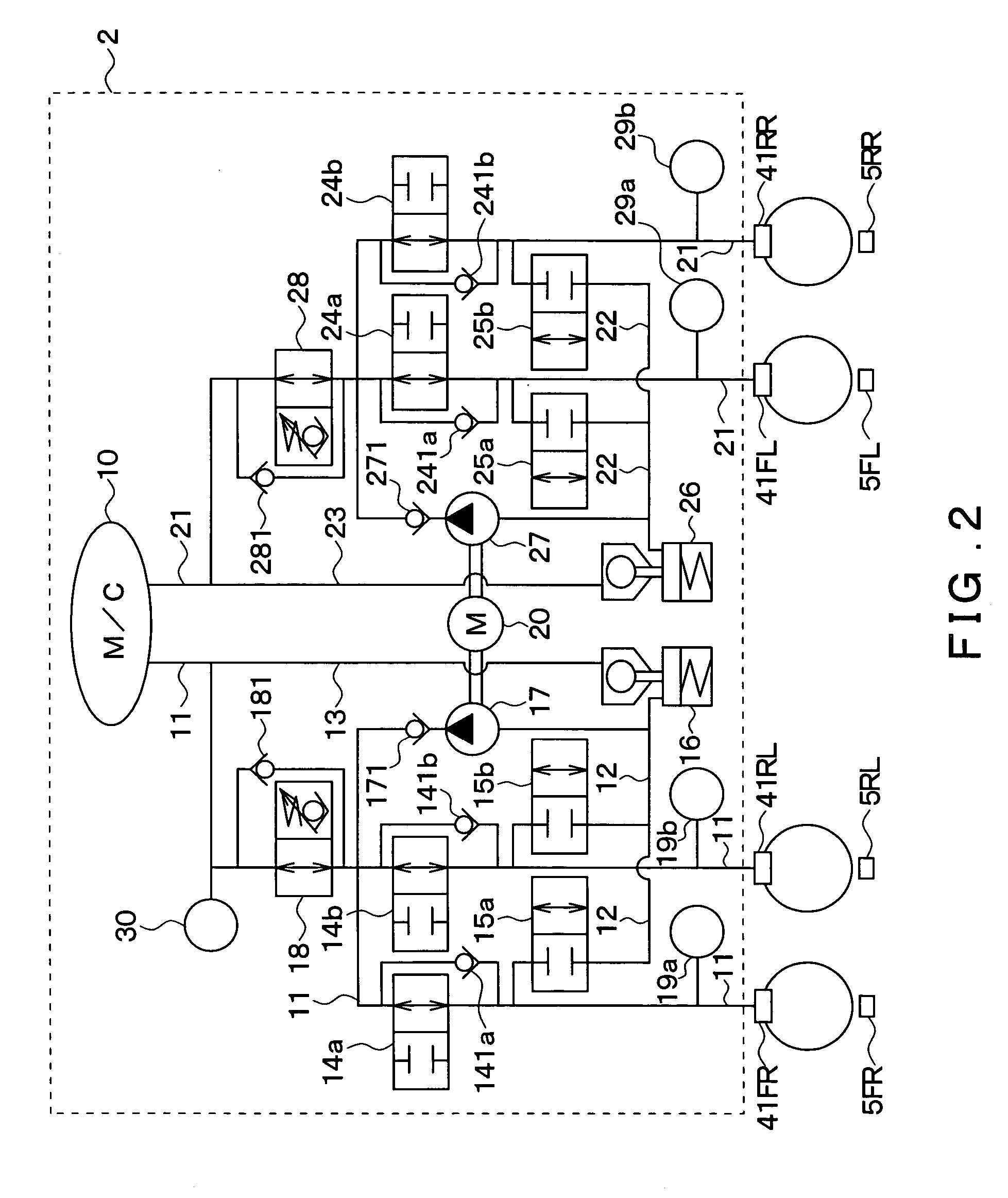
[0038] The parking assist control apparatus according to the present embodiment includes a brake control ECU 1, a hydraulic brake unit 2, an electric automatic parking brake (hereinafter simply referred to as “PKB”) 3, wheel cylinders (hereinafter simply referred to as “W / C”) 41FR, 41RL, 41FL, and 41RR provided on corresponding vehicle wheels 4FR, 4RL, 4FL, and 4RR, wheel speed sensors 5FR, 5RL, 5FL, and 5RR, an in-vehicle LAN bus 6, an engine ECU 7...

second embodiment

[0110] Next, a second embodiment of the present invention will be described. The present embodiment differs from the first embodiment in that the content of the failsafe control routine executed by the brake control ECU 1 has been modified. The structure and the like of the parking assist control apparatus according to the present embodiment are similar to that of the first embodiment. Thus, only the parts that differ will be described here.

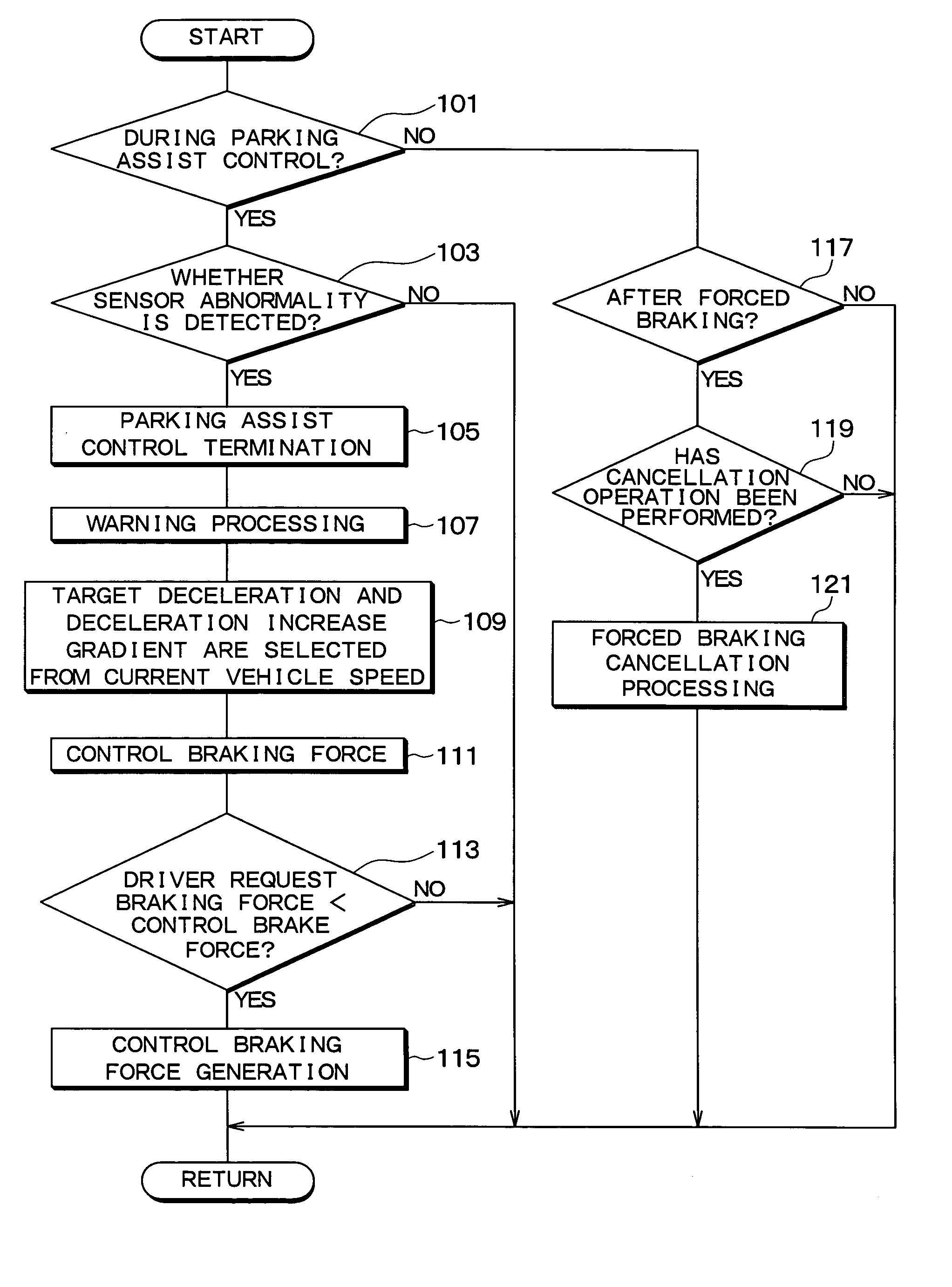
[0111] In the first embodiment, the vehicle VL is forcibly stopped using the hydraulic brake unit 2 when an abnormality occurs in the obstacle sensor 54 which serves as the distance measuring sensor. In the present embodiment, however, the control mode is changed after it is determined whether to continue the parking assist control or forcibly stop the vehicle VL depending on the type of sensor abnormality.

[0112]FIG. 4 is a flowchart illustrating a failsafe control routine executed by the brake control ECU 1 in the parking assist control appara...

third embodiment

[0119] A third embodiment of the present invention will now be described. The present embodiment differs from the first embodiment in that it uses a parking assist control apparatus as a parking assist brake control apparatus that executes parking assist brake control as parking assist control, and that the content of the failsafe control routine executed by the brake control ECU 1 has been modified. The structure and the like of the parking assist brake control apparatus according to the present embodiment is similar to that of the first embodiment. Thus, only the parts that differ will be described here.

[0120] In the present embodiment, the structure itself of the parking assist brake control apparatus is similar to that in the first embodiment. However, the hydraulic brake unit 2 serves as a first brake mechanism of the present invention, and the PKB 3 serves as a second brake mechanism of the present invention.

[0121] In the present embodiment, an abnormality check to detect wh...


PUM


Abstract

When an abnormality is detected in a vehicle side device such as an obstacle sensor during parking assist control, a brake control ECU ends the parking assist control and outputs a control signal to warn the driver while forcibly stopping the vehicle by outputting a first drive signal to a hydraulic brake device and generating braking force.

Description

CROSS REFERENCE TO RELATED APPLICATION [0001] This application is based upon and claims the benefit of Japanese Patent Application No. 2004-163067 filed on Jun. 1, 2004 and No. 2004-163068 filed on Jun. 1, 2004, the content of which are incorporated herein by reference. FIELD OF THE INVENTION [0002] The present invention relates to a parking assist brake control apparatus which applies braking force to wheels of a vehicle when assisting with parking of the vehicle. RELATED ART OF THE INVENTION [0003] In recent years, parking assist control apparatuses have been developed which execute a parking assist control that makes parking a vehicle easy by assisting with parking of the vehicle. For example, there is technology which, when a driver pushes a parking assist switch provided in a vehicle cabin, accordingly automatically moves the vehicle to a parking space and parks the vehicle without the driver having to do anything. There are also technologies, such as that disclosed in Japanese...

Claims


Application Information

Patent Timeline
Patent Type & Authority Applications(United States)
IPC IPC(8): B60T7/00B60T7/22
CPCB60T7/22
Inventor KAMIYA, KAZUHIROMORI, YUKIOKATO, KAZUTAKAMATSUURA, MASAHIRO
Owner ADVICS CO LTD
Why Eureka
Try Eureka