Integrated rotary connector and dynamic RF shield

a technology of dynamic shield and rotary connector, which is applied in the direction of waveguide devices, coupling device connections, aperture leaage reduction, etc., can solve the problems of air gap between and undesirable signal leakage from the join

Inactive Publication Date: 2005-12-01
KEVLIN CORP
View PDF4 Cites 15 Cited by
  • Summary
  • Abstract
  • Description
  • Claims
  • Application Information

AI Technical Summary

Benefits of technology

[0009] The integrated electrical contact and dynamic RF shield comprises a pair of rings, each ring having crenelated cylindrical leaves extending axially therefrom, the rings being coaxially disposed such that their respective leaves are interspersed. Each ring comprises a flange having an outer axial face, for making electrical contact with one of the axial slip contact faces, and an inner axial face acting as a seat for a coil spring disposed in axial compression around the crenelations and between the rings. The spring urges the outer axial faces into firm electrical contact with the slip contact faces to assure electrical continuity across the rotating joint, and the interspersed crenelated leaves provide RF shielding of the air gap surrounded by the connector. Preferably, the crenelated rings are formed of bronze or other suitable non-precious metal or alloy.

Problems solved by technology

A shortcoming of any such arrangement, however, is that, although the arrangement provides an adequate current path across the rotating joint, an air gap exists between the metal housings of the stator and rotor, which function additionally as the RF shielding for the joint.
The missing shielding permits undesirable signal leakage from the joint through the gap.

Method used


Image

  • Integrated rotary connector and dynamic RF shield
  • Integrated rotary connector and dynamic RF shield
  • Integrated rotary connector and dynamic RF shield

Examples


Embodiment Construction

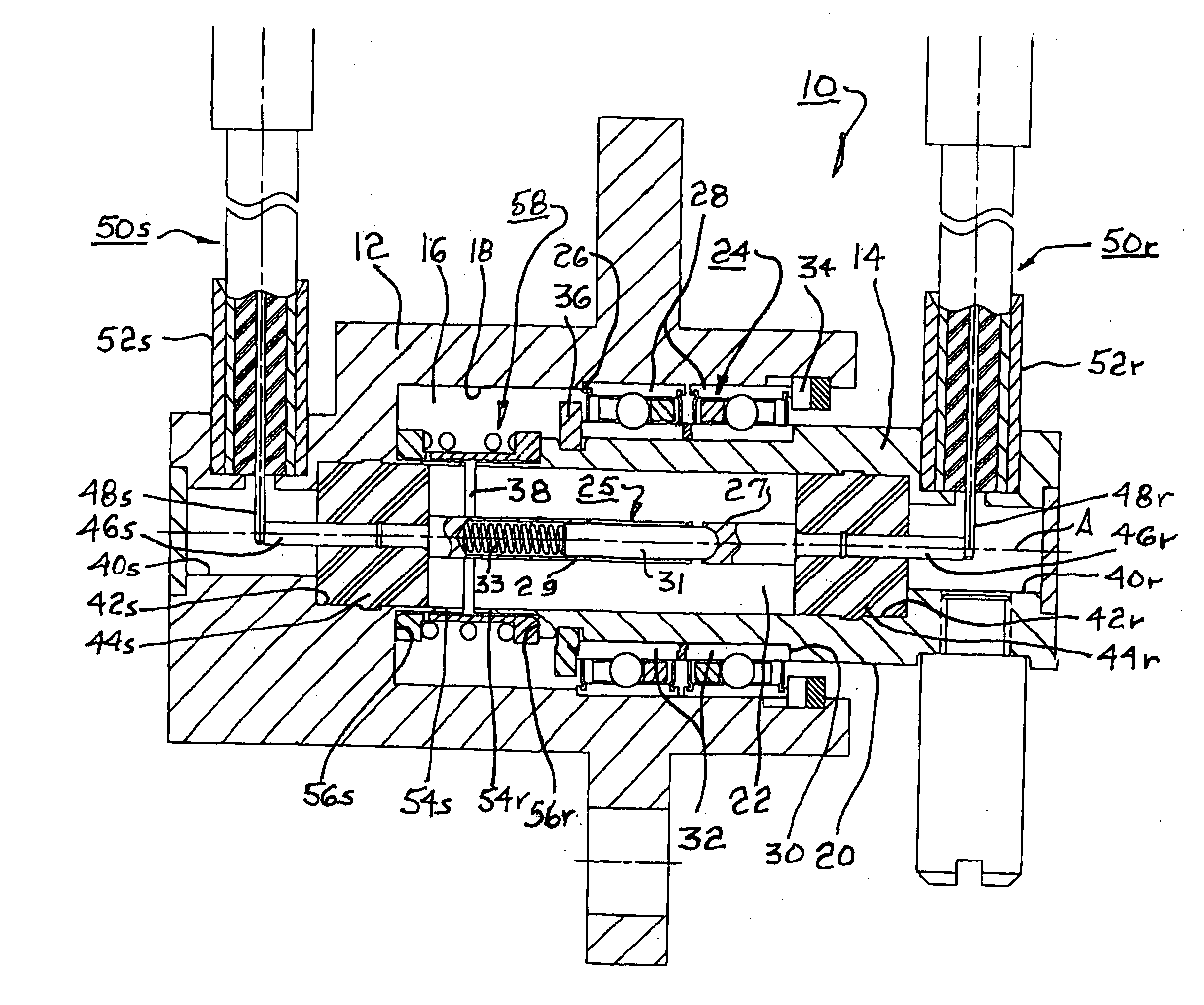
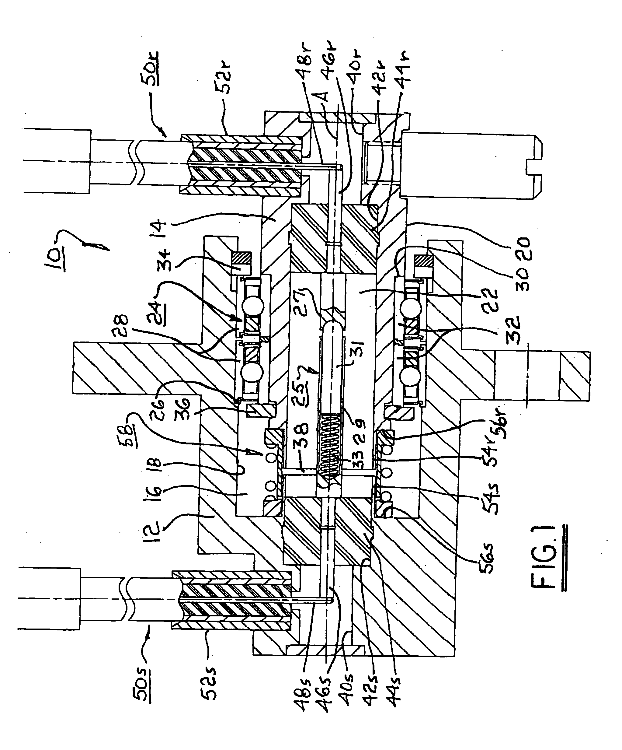
[0013] Referring to FIG. 1, a rotary cable connector assembly 10 in accordance with the invention includes a stator body 12 and a rotor body 14. It should be noted that the terms “stator” and “rotor” are arbitrary and in any given application either of elements 12 and 14 may be fixed and the other rotational relative thereto. Stator body 12 includes a first cylindrical well 16 having an inner wall 18. Rotor body 14 has a stepped outer surface 20 and includes a second cylindrical well 22. A duplex ball bearing assembly 24 is disposed between wall 18 and surface 20 to permit bodies 12,14 to rotate axially of each other as desired. Preferably, wall 18 is stepped 26 to receive outer bearing races 28, and surface 20 is similarly stepped 30 to receive inner races 32. The bearing assembly 24 is bounded by first annular stops 34,36 mounted on wall 18 and surface 20, respectively, defining the axial relationship between stator body 12 and rotor body 14 and an axial air gap 38 therebetween.

[...


PUM


Abstract

A rotary cable connector assembly for connecting coaxial waveguides. The assembly includes a metal stator having a counterbored well and a metal rotor extending coaxially into the well. An axial air gap is formed between the stator and rotor which each contain a conventional dielectric sleeve and center element for mating conventionally to carry a signal therebetween. An electrical connector/dynamic RF shield for providing an electrical path across the rotary joint and for shielding the air gap includes a pair of rings having crenelated cylindrical leaves extending axially toward each other and being interspersed. Each ring has a face for making electrical contact with the stator and rotor. A spring urges the rings into contact with the stator and rotor. The crenelated leaves provide RF shielding of the air gap surrounded by the shield. The rings are formed of bronze or other non-precious metal or alloy.

Description

TECHNICAL FIELD [0001] The present invention relates to rotatable electrical contact devices; more particularly, to such devices for permitting rotation of coaxial cable connections; and most particularly, to an improved rotatable contacting electrical connector and RF shield for a coaxial cable. BACKGROUND OF THE INVENTION [0002] Devices for permitting rotation of coaxial cable connections between a stator assembly and a rotor assembly are well known. These devices provide a current path through the rotating joint typically through the use of a slip ring connector. The device must also protect the circuit from undesirable RF interference. See, for example, U.S. Pat. Nos. 4,020,431; 4,298,850; and 5,805,115. [0003] In the last-cited patent, a rotary joint for coaxial cable is disclosed and shown in FIG. 7 therein. A stationary tubular metal center conductor is disposed in a cylindrical dielectric sleeve within a metal stator. A metal rotor includes a similar cylindrical dielectric s...

Claims


Application Information

Patent Timeline
Patent Type & Authority Applications(United States)
IPC IPC(8): H01P1/06H01R13/646H01R13/658H01R35/00H03H9/64H05K9/00
CPCH01P1/066H01R24/542H01R35/00H01R13/6585H05K9/0018H01R13/6581H01R2103/00
Inventor FAULKNER, G. DAVIDSPELLENBERG, KEITH W.MCLAUGHLIN, BRIAN P.
Owner KEVLIN CORP
Why Eureka
Try Eureka