Plasma processing system and use thereof

a processing system and technology of plasma, applied in the field of plasma processing system, can solve the problems of abnormal discharge, gap between the electrode plate and the support member, and power, however, may be wasted due to discharg

Inactive Publication Date: 2008-12-11
TOKYO ELECTRON LTD +1
View PDF7 Cites 20 Cited by
  • Summary
  • Abstract
  • Description
  • Claims
  • Application Information

AI Technical Summary

Benefits of technology

[0012]Therefore, an electromagnetic wave at 1 GHz or less, for example, may be used to excite the uniform and stable plasma from a single F-based gas. The single F-based gas may not be effective in exciting the uniform and stable plasma with a certain degree of power o...

Problems solved by technology

Unfortunately, the above configuration may provide a gap between the electrode plate and the support member.
The plasma may enter the gap, causing an abnormal discharge.
The power, however, may be wasted due to the discharge.
The discharge may damage the O-ring.
Heat from the discharge may generate cracks of the electrode plates including dielectric materials.
It is costly to acc...

Method used


Image

  • Plasma processing system and use thereof
  • Plasma processing system and use thereof
  • Plasma processing system and use thereof

Examples


first embodiment

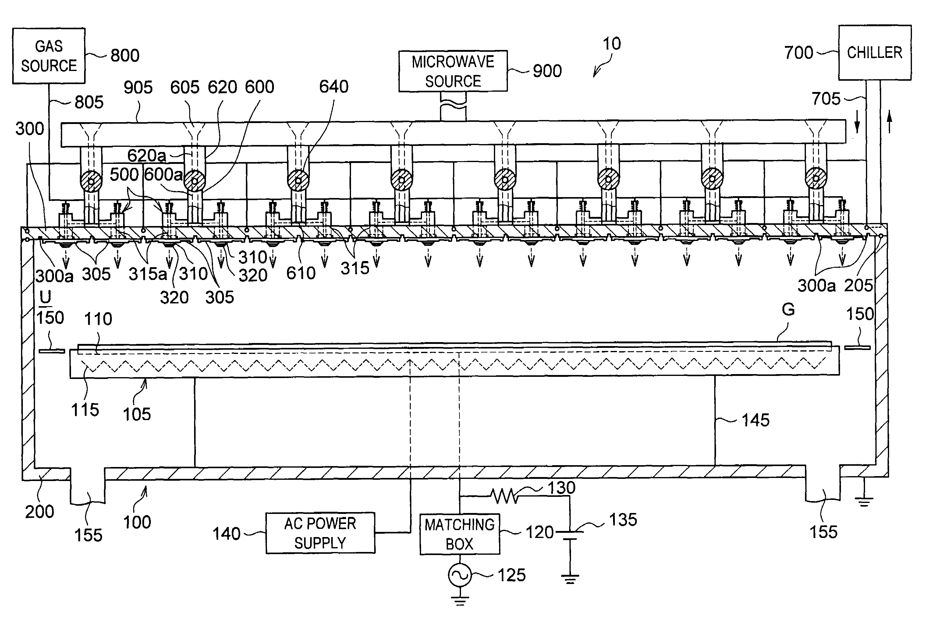
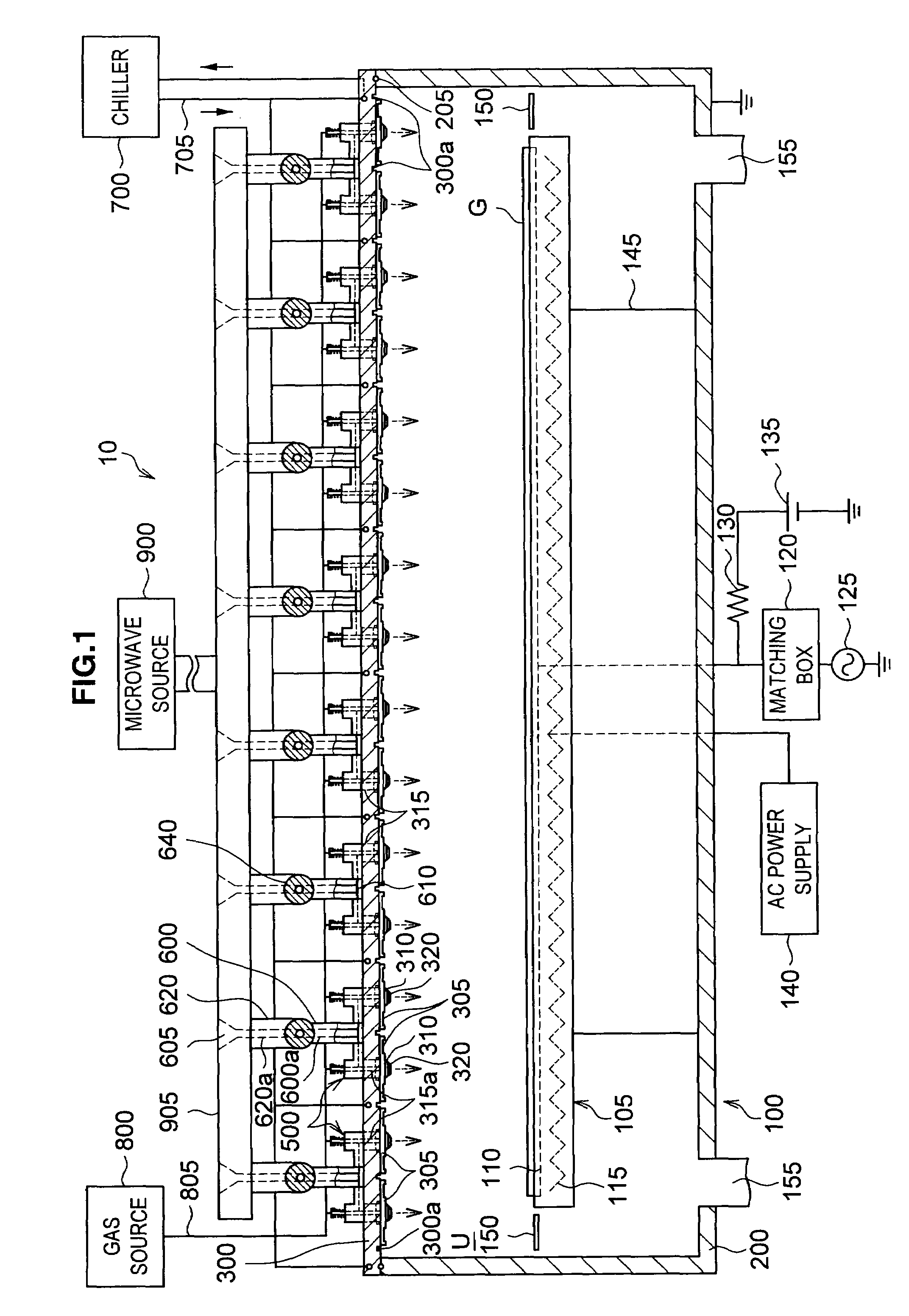
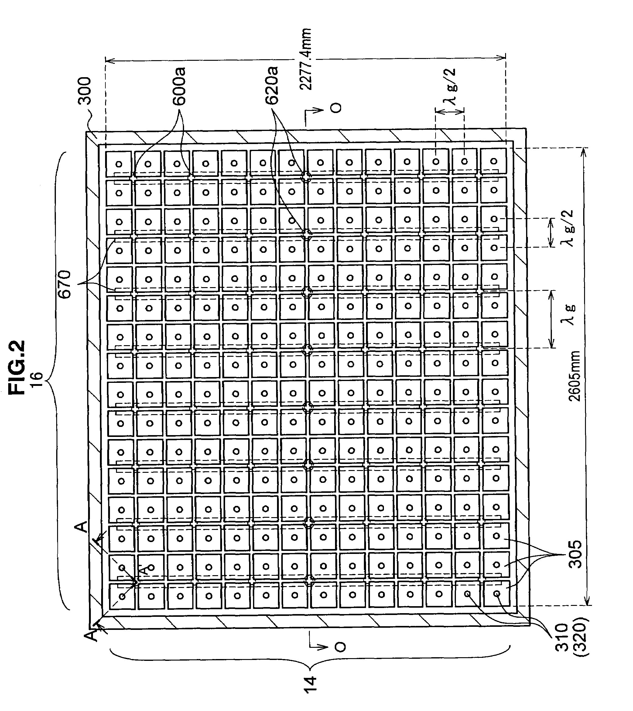
[0025]With reference to FIGS. 1 and 2, a plasma processing system according to a first embodiment of the present invention will be described below. FIG. 1 schematically shows a vertical cross-sectional view of the system (a cross-section taken along the O-O in FIG. 2). FIG. 2 shows the ceiling surface of the processing chamber. Note that, in the following discussion and accompanying drawings, the elements having the same configuration and function are provided with the same reference symbol and their description are omitted.

(Configuration of Plasma Processing System)

[0026]A plasma processing system 10 includes a processing chamber 100 in which a plasma process is applied to a glass substrate (“substrate G”). The processing chamber 100 includes a chamber main portion 200 and a lid 300. The chamber main portion 200 has a bottom-closed cube shape with an opening formed on the top thereof. The opening is closed by the lid 300. On the contact surface between the chamber main portion 200 ...

second embodiment

Modification of Second Embodiment

[0071]The modifications of the second embodiment include the following modifications 1 and 2.

modification 1

(Modification 1)

[0072]FIG. 7 shows a plasma processing system 10 in a modification 1. The system 10 in the modification 1 differs from the system 10 in the second embodiment as follows. The system 10 in the second embodiment only includes the evacuation pipe 545. In contrast, the system 10 in the modification 1 includes the evacuation pipe 545 and a gas supply pipe 550. The pipes 545 and 550 both communicate with the space S between the dielectric ring 410 and the dielectric ring 525.

[0073]Specifically, in the plasma processing system 10 in the modification 1, the gas supply pipe 550 and the evacuation pipe 545 connect to the gas source 800 and pass through the lid 300 to communicate with the space S. The gas source 800 fills an inert gas (such as an argon gas) in the space S through the gas supply pipe 550. The inert gas presses away the atmosphere in the space S through the evacuation pipe 545. The atmosphere of the space S is thus replaced by the inert gas. This may reduce the in...


PUM

PropertyMeasurementUnit
Frequencyaaaaaaaaaa
Forceaaaaaaaaaa
Dielectric polarization enthalpyaaaaaaaaaa

Abstract

A plasma processing system 10 includes a processing chamber 100, a microwave source 700 that outputs a microwave, a coaxial waveguide 315 that transfers the microwave from the microwave source, a plurality of dielectric plates 305 that transmit the microwave transferred through the coaxial waveguide 315 and discharge the microwave into the processing chamber 100, and a metal electrode 310 having a first end and a second end, the first end coupled to the coaxial waveguide 315, the second end disposed on the surface of the dielectric plate 305 facing the substrate. The coaxial waveguide 315 holds the dielectric plate 305 and metal electrode 310 and is securely fastened by a fastening mechanism 500. The coaxial waveguide 315 is given a force by the spring member 515, the force being directed away from the processing chamber 100.

Description

CROSS-REFERENCE TO RELATED APPLICATION[0001]The present invention contains subject matter related to Japanese Patent Application JP 2007-153552, filed in the Japan Patent Office on Jun. 11, 2007, the entire contents of which being incorporated herein by reference.FIELD OF THE INVENTION[0002]The present invention relates to a plasma processing system that excites a gas using an electromagnetic wave and applies a plasma process to a target object, and more particularly, to a method of fastening a dielectric material.BACKGROUND OF THE INVENTION[0003]Plasma processing systems needs power to excite a gas supplied in the processing chambers to generate the plasma. A dielectric plate is generally used to supply power to the processing chamber. An example plasma processing system includes an upper electrode and a lower electrode opposed to each other in the processing chamber. The upper electrode is applied with a high-frequency electric power to ionize a process gas into a plasma in the pr...

Claims


Application Information

Patent Timeline
IPC IPC(8): C23F1/02C23C16/513H05H1/46
CPCC03C17/002C23C16/4405C23C16/511H01J37/32082H01J37/32238H05H1/46
Inventor HIRAYAMA, MASAKIOHMI, TADAHIRO
Owner TOKYO ELECTRON LTD
Why Eureka
Try Eureka