Filter

a filter and millimeter wave technology, applied in the field of filters, can solve the problems of deterioration of characteristics by connection, difficult to insert cavity resonators into microwave circuits, and difficulty in modifying the layout of microwave circuits, so as to improve matching characteristics, prevent mutual interference between filters and circuits in series, and prevent the effect of deterioration of characteristics

Inactive Publication Date: 2005-12-01
NEW JAPAN RADIO CORP
View PDF5 Cites 10 Cited by
  • Summary
  • Abstract
  • Description
  • Claims
  • Application Information

AI Technical Summary

Benefits of technology

[0013] In at least one end side of the input terminal and output terminal, a reactance member, which narrows the waveguide groove, is provided inside the waveguide groove, thereby the impedance matching is achieved. The matching characteristics are thus improved, and mutual interference between the filter and circuit in series can be prevented. Through providing the reactance member, which narrows the waveguide, at a portion of at least one side of wider surface and narrower surface of the waveguide, matching characteristics can be improved.
[0014] Through forming a partition plate, which divides input side and output side of the U-shaped waveguide groove, so as to project from the same surface formed by the input terminal and output terminal, electric connection between the circuit in series and filter can be certainly carried out. Therefore, deterioration of characteristics by the connection can be prevented, since there is no gap inbetween.
[0015] According to the filter of the present invention, the waveguide groove is formed in U-shape and input terminal and output terminal are formed on the same surface. Therefore, even if the full length of the filter has the same characteristics as the conventional arrangement with a straight connection of resonators, it is possible to arrange the filter having the desired characteristics with substantially half in length. In addition, since input and output terminals are formed on the same surface, through grouping the input terminal and output terminal on the same surface of the microwave circuit side, the filter can be certainly inserted into the microwave circuit by only attaching the filter with a screw without putting into the microwave circuit. Accordingly, it is possible to replace filters without affecting the microwave circuit if the length of the layer (number of resonators) is increased to obtain the high performance of the filter or the length is decreased. Furthermore, since it is possible to connect resonators without giving any load for the microwave circuit, the microwave circuit and filter are not deformed, and transmission characteristics and filter characteristics are not deteriorated.

Problems solved by technology

Accordingly, there has been a problem that it becomes extremely difficult to insert the cavity resonators into a microwave circuit.
In addition, it is impossible to build the multiple layers of iris plates into the waveguide, and the waveguide is required to be connected after being divided by a center line in an axis direction or separating the wider surface and connected with the iris plates.
Therefore, the layout of the microwave circuit has to be modified, since multiple layers of resonators become longer and are difficult to be inserted into the existing circuit (microwave circuit).
In addition, there have been problems of leakage of radio wave or characteristic deterioration in case there is space between the filter and existing circuit, and there have been problems of characteristic deterioration in the case there is the deformation of the microwave circuit by forcible fastening to avoid the space.
However, in the case the microwave circuit is already built in replacing filters, there is a problem that a different filter cannot be built in for improving the filter characteristics.
However, there has been a problem that space efficiency is extremely declined, since multiple layers of cavity resonators become extremely long in the case they are connected in a straight line, and large area is occupied even if propagation direction is bent at 90°.

Method used


Image

  • Filter
  • Filter
  • Filter

Examples


Embodiment Construction

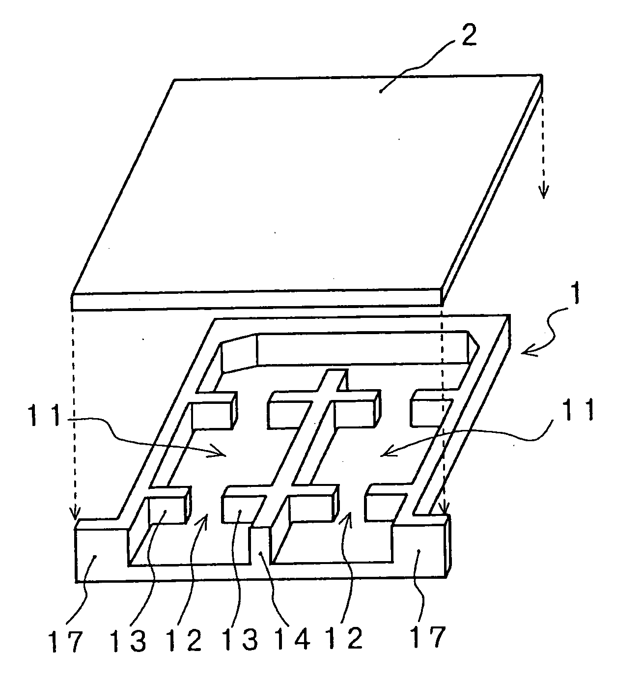
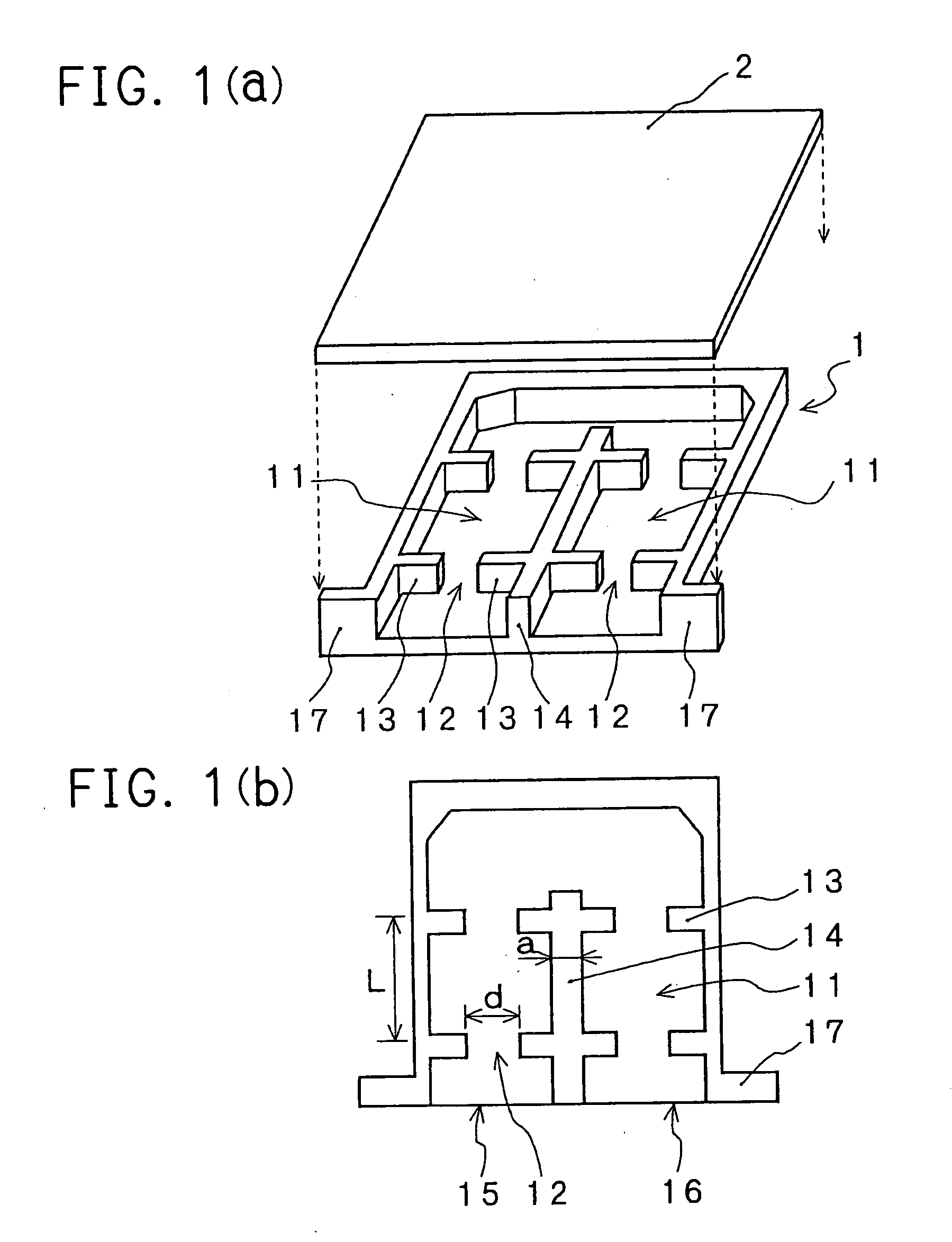
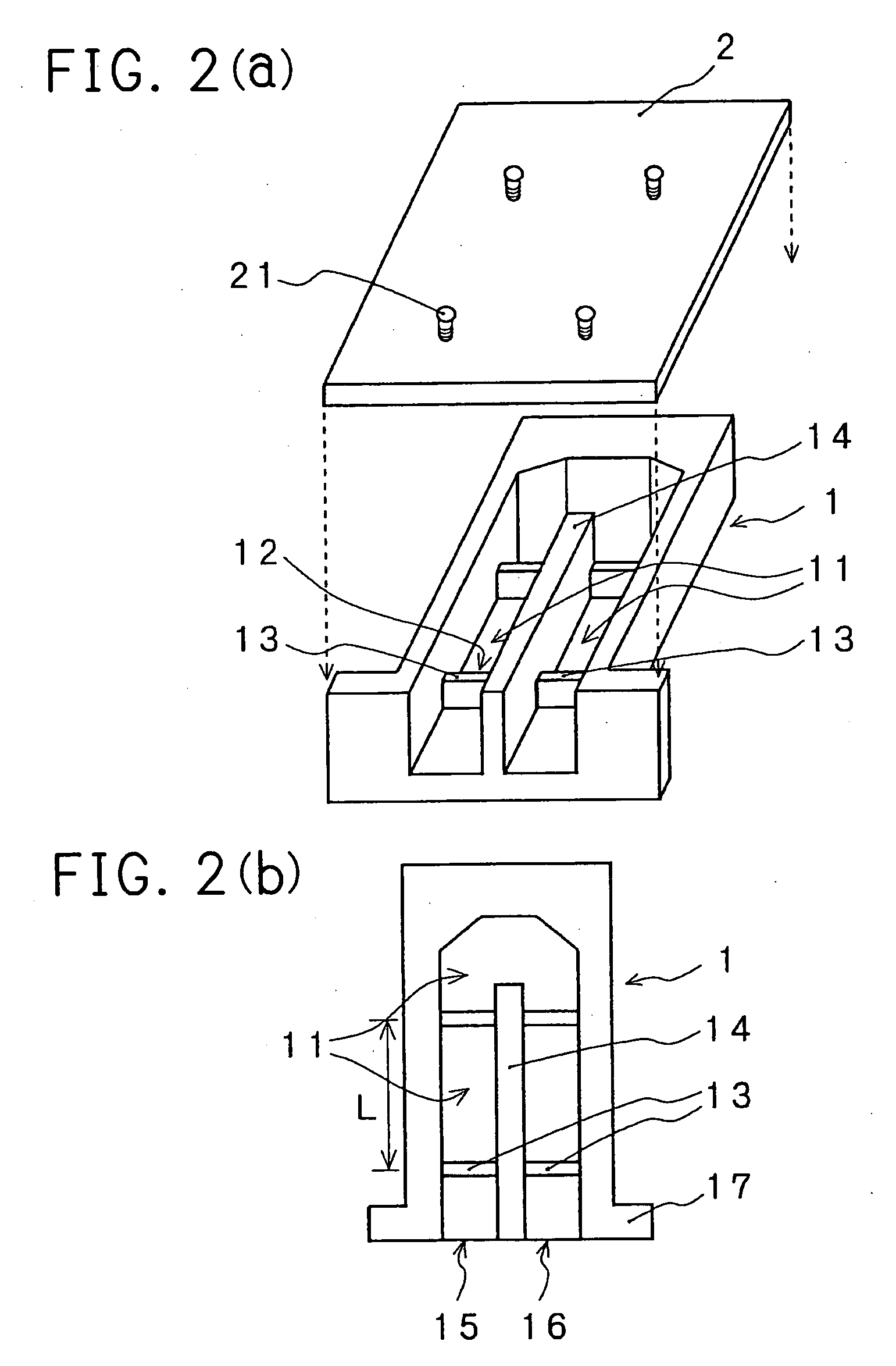
[0023] The filter of the present invention is illustrated by referring to figures. In FIGS. 1 (a) and (b), there are illustrated an exploded perspective view of one Embodiment of the present invention and a plan view with a cover being removed. A waveguide groove 11 with one surface being open is formed in a U-shape on a body 1, and a plurality of inductive resonant windows is provided at a predetermined interval inside the waveguide groove 11 along a longitudinal direction. A waveguide having the inductive resonant windows 12 is formed by providing a cover 2 on the surface of body 1 as closing the open surface. A cavity, which is enclosed by the two adjacent inductive resonant windows 12 provided along a longitudinal direction of the waveguide 11, body 1 and cover 2, resonates at a predetermined frequency band, and a plurality of inductive resonant windows 12 is provided to pass electromagnetic wave in a predetermined frequency band. An end of the U-shaped waveguide 11 is to be an ...


PUM


Abstract

A filter including a body on which a waveguide groove, whose one surface is open, is formed in a U-shape and a plurarity of inductive resonant windows are provided along a longitudinal direction of the waveguide groove at a predetermined interval in the waveguide groove; and a cover being provided on a top surface of the body so as to cover the surface being open, wherein the plurality of inductive resonant windows are provided in such a manner that a cavity, which is enclosed by two of the plurality of inductive resonant windows being adjacent, the body and cover, resonates at a predetermined frequency and passes a electromagnetic wave in a predetermined frequency band and wherein one end of the U-shaped waveguide groove is an input terminal and other end is an output terminal, and the input terminal and output terminal are formed on a same surface.

Description

BACKGROUND OF THE INVENTION [0001] The present invention relates to a filter for microwave and millimetric wave which passes desired frequency bands and interrupts unnecessary frequency bands. More particularly, the present invention relates to the filter which saves disposing space through employing a waveguide and enables to simplify and ensure to build into a microwave circuit. [0002] As for a band-pass filter employing a cavity, there has been a known filter whose arrangement is shown in schematic view in FIG. 5. In this arrangement, an iris plate 32 is inserted into a rectangular waveguide 31, and the iris plate 32 acts as an inductive resonant window (reactance element) and plurality pairs of resonant windows are provided along tube axis direction. A cavity resonator is arranged by the space between two adjacent resonant windows in the longitudinal direction and a tube wall of the rectangular waveguide 31. The iris plate 32 is provided to obtain desired band characteristics th...

Claims


Application Information

Patent Timeline
Patent Type & Authority Applications(United States)
IPC IPC(8): H01P1/207H01P1/208
CPCH01P1/208H01P1/207
Inventor OBATA, HIDEYUKI
Owner NEW JAPAN RADIO CORP
Why Eureka
Try Eureka