Wireless tire pressure and/or wheel speed sensing system for aircraft

a technology of aircraft tire pressure and sensing system, which is applied in the direction of aircrafts, devices using electric/magnetic means, transportation and packaging, etc., can solve the problems of premature replacement, excessive tire wear, and high cost of premature replacement of aircraft tires

Inactive Publication Date: 2005-12-01
ROSEMOUNT AEROSPACE
View PDF33 Cites 30 Cited by
  • Summary
  • Abstract
  • Description
  • Claims
  • Application Information

AI Technical Summary

Problems solved by technology

It is well known that improper inflation will cause excessive wear on tires and lead to premature replacement thereof.
This is especially important in the aircraft industry where premature replacement of aircraft tires is particularly expensive.
Taking off and landing on improperly inflated tires may lead to aircraft accidents.
However, each time the pressure is tested with such a pressure gauge a small amount of air is released from the tire.
Thus, over a number of inspections, the tire will become under inflated and will require re-inflation which is a timely and costly maintenance process.
As with any moving part, the pneumatic spinning coupler suffers from wear with time which may lead to air pressure leakage.
Such a system is considered rather bulky and expensive.
In addition, the accuracy of the electrical pressure signal is vulnerable to environmental changes at the wheel which may vary in temperature from −50° C. to approximately 150° C., for example., and be exposed to inclement weather conditions as well.

Method used


Image

  • Wireless tire pressure and/or wheel speed sensing system for aircraft
  • Wireless tire pressure and/or wheel speed sensing system for aircraft
  • Wireless tire pressure and/or wheel speed sensing system for aircraft

Examples


Embodiment Construction

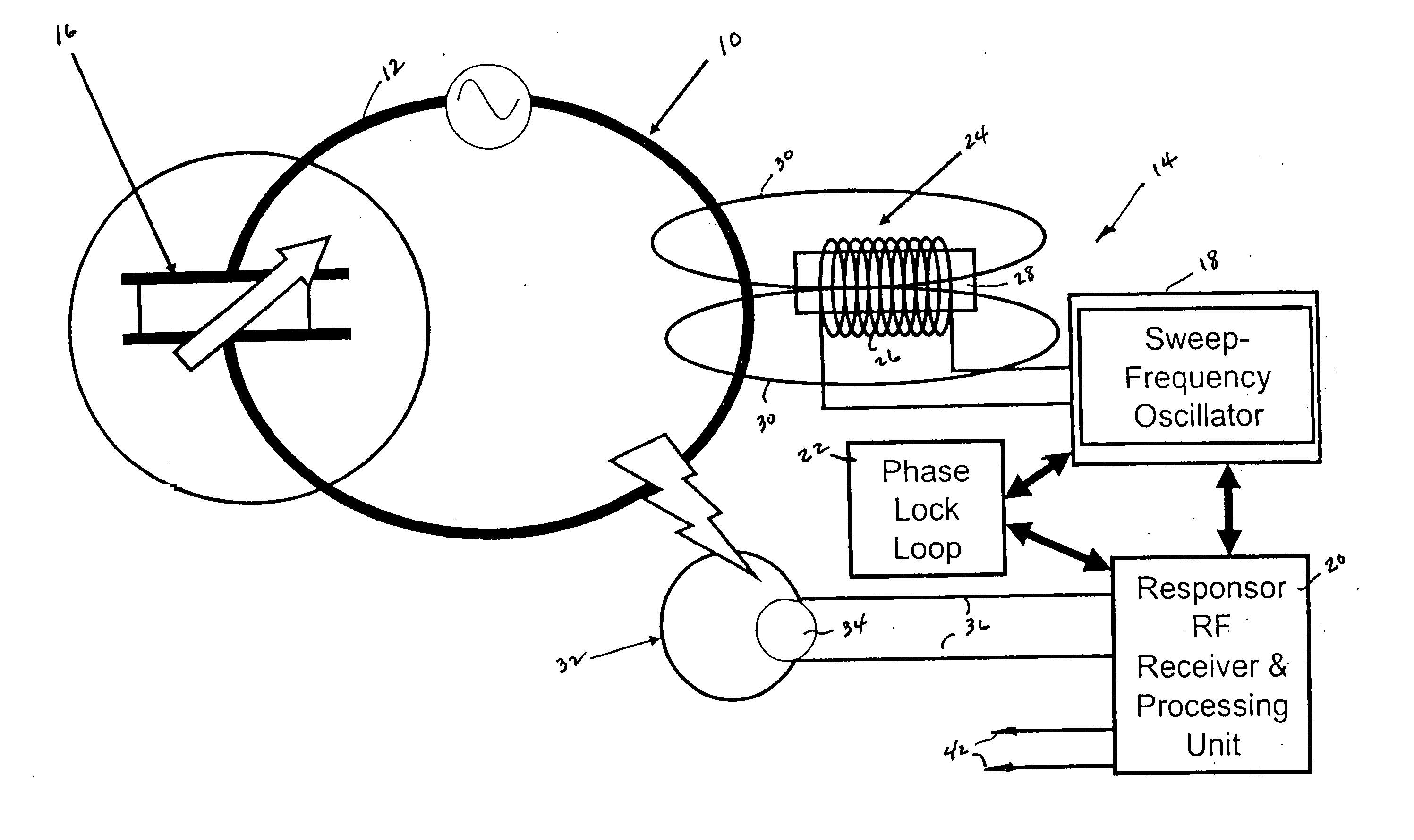
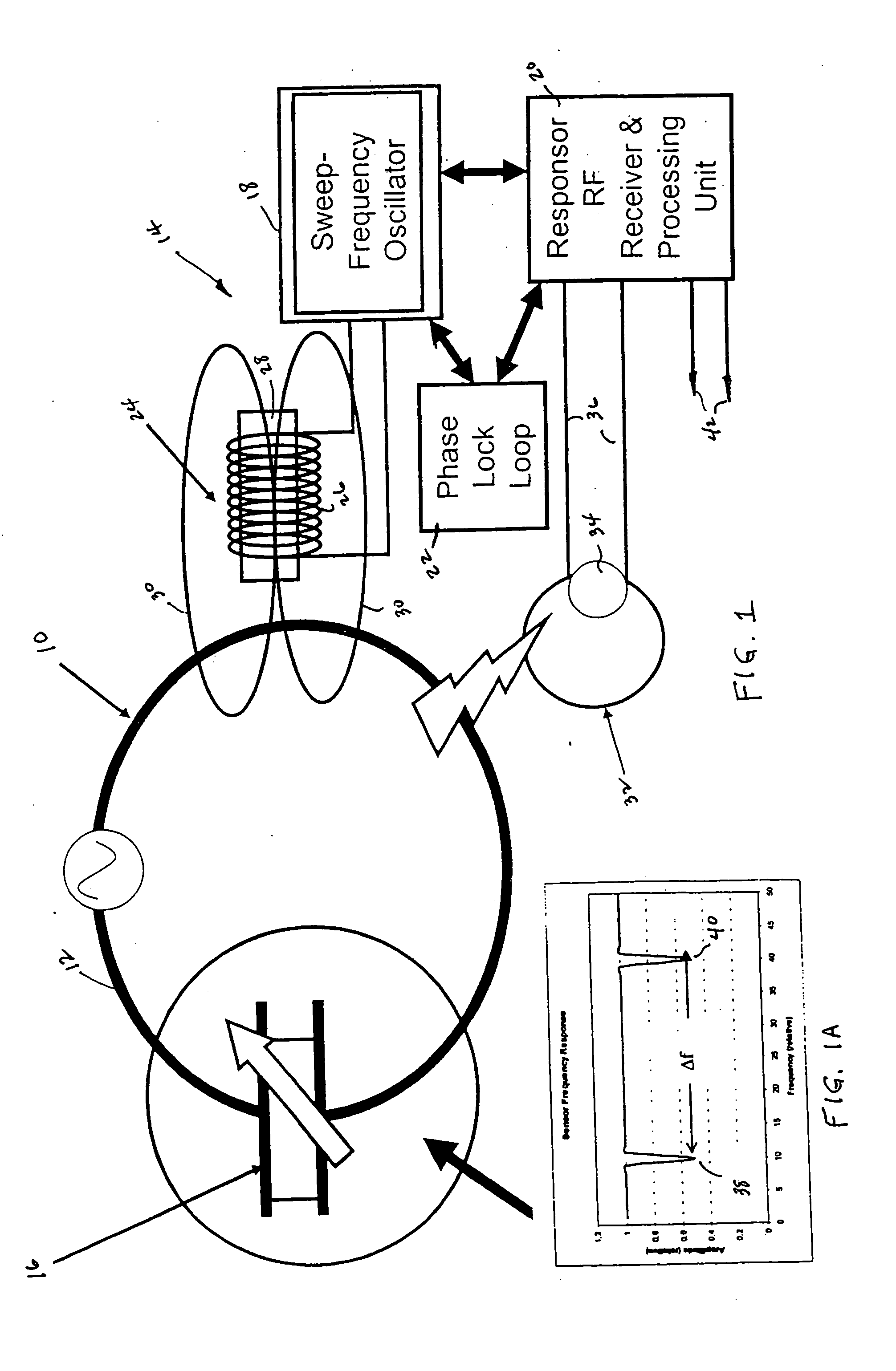
[0030] An embodiment of the wireless tire pressure sensing system in accordance with one aspect of the present invention comprises two parts. One part is made up of dual, aircraft wheel mounted, resonant circuits. One of the dual resonant circuits varies in resonant frequency as tire pressure, temperature and other parameters vary and the other or reference resonant circuit varies in resonant frequency only with temperature and other parameter variations. The second part of the system is an aircraft landing gear mounted or handheld exciter unit that generates a variable frequency magnetic field to excite the wheel mounted pressure and reference resonant circuits and determines the resonant frequencies thereof as will become better understood from the description below.

[0031] In the present embodiment, each resonant circuit comprises an inductor, which is formed by a loop of wire of conductive material, like copper, for example, and a variable capacitor sensor configured in a tank c...


PUM


Abstract

A wireless tire pressure sensing system for an aircraft comprises: dual resonant circuits mounted to a wheel of the aircraft, each resonant circuit comprising: a variable capacitance sensor and a wire loop of a predetermined inductance coupled thereto, one capacitance sensor for monitoring the pressure of a tire mounted to the wheel, and the other capacitance sensor operative as a reference to the one capacitance sensor; an interrogating circuit magnetically coupleable to the dual resonant circuits and operative to induce magnetically a variable frequency current in the dual resonant circuits, the one resonant circuit responding to the induced current with an E-field signal at a first resonant frequency commensurate with the capacitance of the one sensor, and the other resonant circuit responding to the induced current with an E-field signal at a second resonant frequency commensurate with the capacitance of the other sensor; a receiving circuit E-field coupleable to the dual resonant circuits and operative to receive the E-field signals at the first and second resonant frequencies and to generate first and second signals representative thereof, and a processing circuit coupled to the receiving circuit for processing the first and second signals to generate a compensated pressure reading of the tire. The pressure sensing system may be modified to provide and / or include wheel speed sensing.

Description

BACKGROUND OF THE INVENTION [0001] The present invention is related to aircraft tire pressure and wheel speed sensing, in general, and more particularly to a wireless tire pressure and / or wheel speed sensing system for aircraft. [0002] It is well known that improper inflation will cause excessive wear on tires and lead to premature replacement thereof. Keeping a tire at its manufacture's recommended inflation pressure will extend the life of the tire. This is especially important in the aircraft industry where premature replacement of aircraft tires is particularly expensive. Safety is another consideration. Taking off and landing on improperly inflated tires may lead to aircraft accidents. Accordingly, checking for proper tire pressure is a mandatory part of the preflight inspection of the aircraft. [0003] Generally, during preflight inspection, a conventional pneumatic-mechanical pressure gauge is used manually to check the tire pressure through a valve stem. However, each time th...

Claims


Application Information

Patent Timeline
Patent Type & Authority Applications(United States)
IPC IPC(8): B60C23/04
CPCB60C23/0428G01P3/48G01P3/44B60C23/043B60C2200/02
Inventor MYHRE, DOUGLAS C.BUENZ, MARK J.NORLIEN, JOHN A.KUNIK, WILLIAM G.WILLIAMS, WADE W.
Owner ROSEMOUNT AEROSPACE
Why Eureka
Try Eureka