Planar array antenna

a technology of array antennas and antennas, applied in the direction of individual energised antenna arrays, resonant antennas, radiating elements structural forms, etc., can solve the problem of difficult planar construction of antennas including feeding systems, and achieve the effect of promoting the surfaceness of antennas

Inactive Publication Date: 2005-12-01
NIHON DEMPA KOGYO CO LTD +1
View PDF4 Cites 21 Cited by
  • Summary
  • Abstract
  • Description
  • Claims
  • Application Information

AI Technical Summary

Benefits of technology

[0020] According to the above described configuration, since the feeding is made to the first and second slot lines by the fifth and sixth microstrip lines, the feeding system can be configured by transmission lines only, and there is no need for the functional devic

Problems solved by technology

Eventually, in the case of the planar array antenna shown in FIGS. 1A and 1B, it is difficult to constitute a feeding system by the microstrip lines, while sharing

Method used


Image

  • Planar array antenna
  • Planar array antenna
  • Planar array antenna

Examples


first embodiment

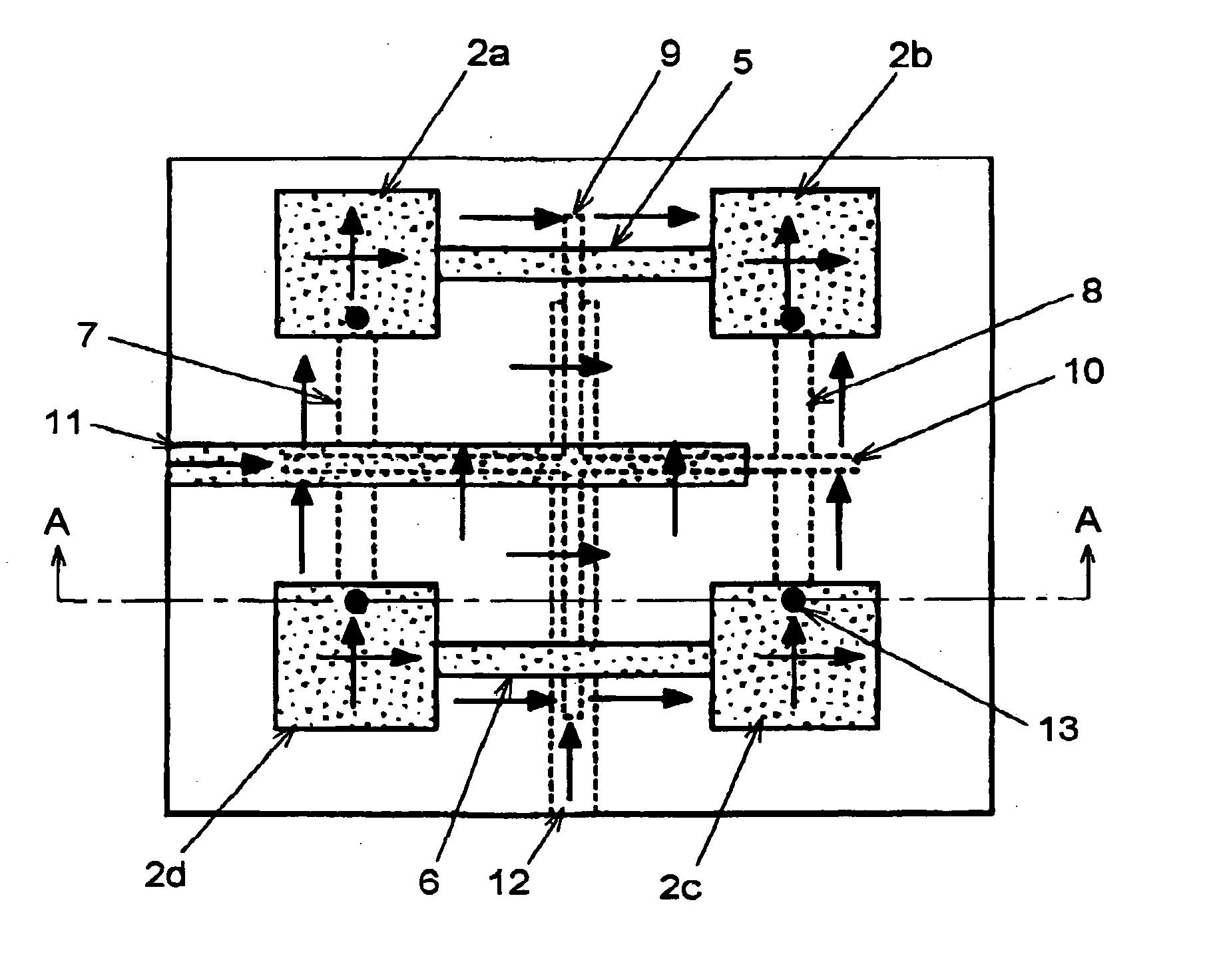
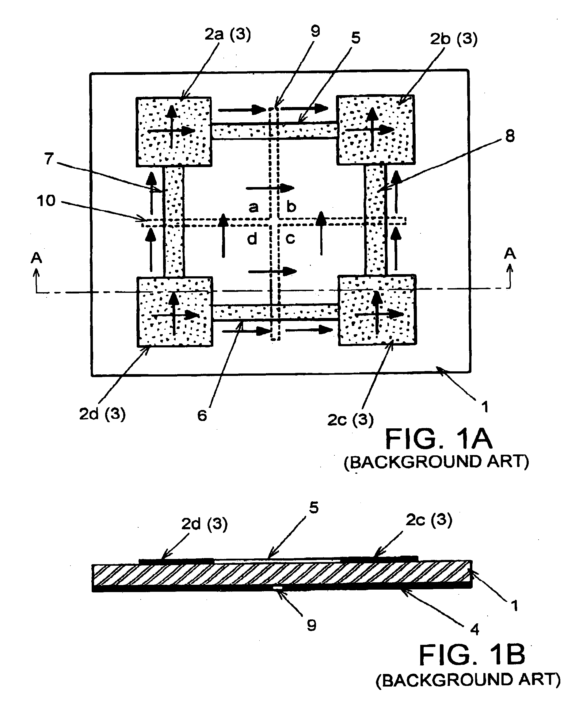
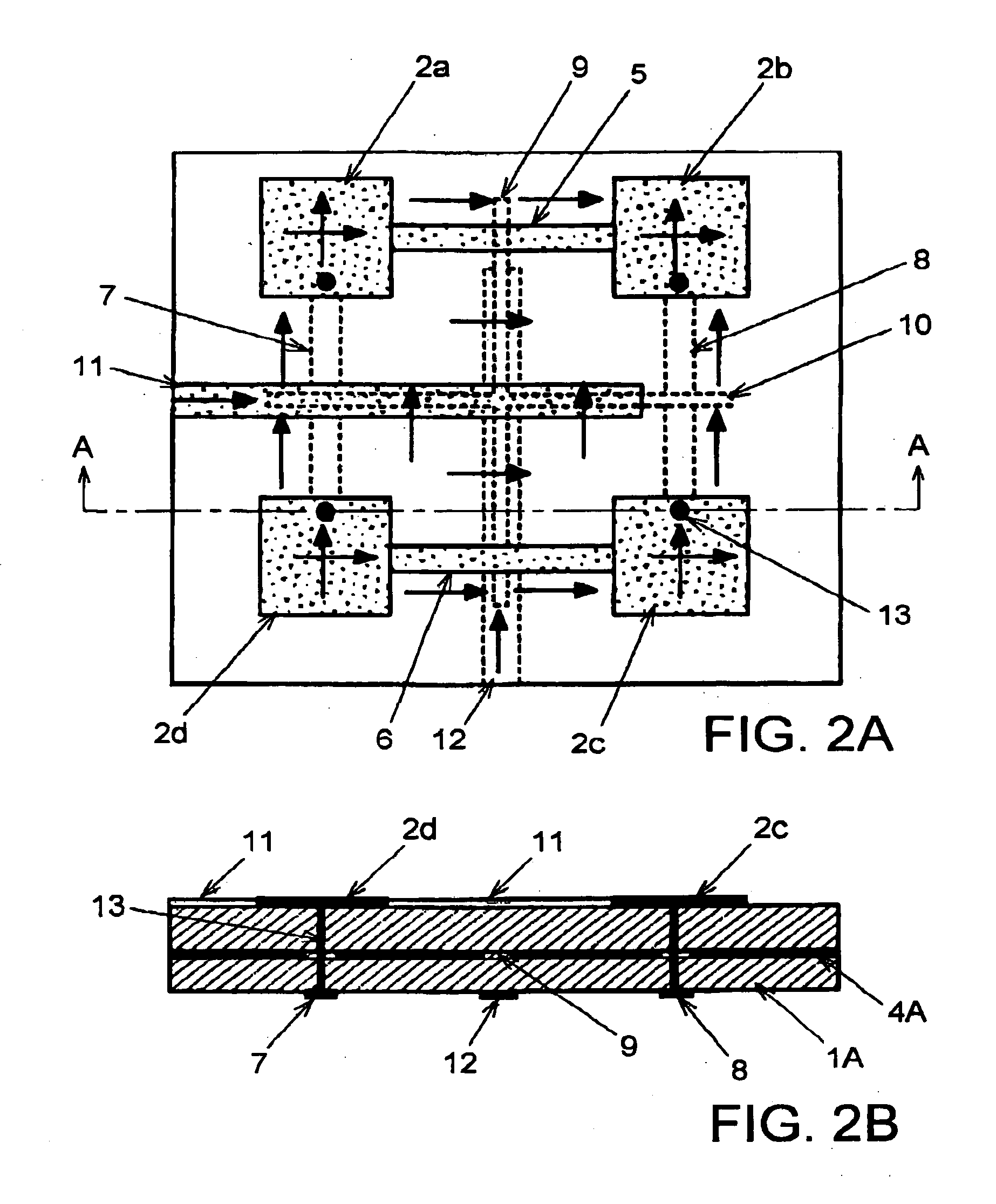
[0038]FIGS. 2A and 2B illustrate a planar array antenna according to the present invention. In FIGS. 2A and 2B, the same reference numerals will be attached to the same constituent components as those in FIGS. 1A and 1B, and the repeated description thereof will be omitted.

[0039] The planar array antenna of the first embodiment illustrated in FIGS. 2A and 2B is configured by using multi-layer substrate 1A having intermediate layer conductor 4A. Multi-layer substrate 1A is laminated In two layers with a dielectric substrate, and intermediate layer conductor 4A is formed across an almost entire plane of the laminated face of the two dielectric substrates. Intermediate layer conductor 4A is made of a metal foil and functions as a ground conductor In microstrip lines. A first principal surface of multi-layer substrate 1A, similarly to those shown in FIGS. 1A and 1B, is disposed with four antenna elements 2a to 2d of a microstrip line type corresponding to the corners of a geometrically ...

third embodiment

[0056]FIGS. 5A to 5C illustrate a planer array antenna according to the present invention. FIG. 5C is equivalent to a view seen through from above the planar array antenna Illustrated in FIG. 5A, and depicts the components at the rear surface side by a solid line.

[0057] In this planar array antenna, a basic configuration in which a feeding system is comprised of mutually orthogonal first and second slot lines 9 and 10 which are provided in intermediate layer conductor 4A of the laminated face of multi-layer substrate 1A is the same as the above described embodiments. In the third embodiment, without using via holes and air bridges by conducting wires, the feeding to each of antenna elements 2a to 2d from two orthogonal directions, that is, horizontal and vertical directions, is made possible.

[0058] Four corners of one principal surface in multi-layer substrate 1A is formed with four antenna elements 2a to 2d of a microstrip line type, and openings 16 are formed at a corresponding p...

fourth embodiment

[0061]FIGS. 6A to 6C illustrate a planar array antenna according to the present invention. FIG. 6C is equivalent to a view seen through from above the planar array antenna shown in FIG. 6A, and depicts the components of the rear surface side by a solid line.

[0062] The planar array antenna according to the fourth embodiment is different from the third embodiment in that, while the feeding is made without using via holes and air bridges as those of the third embodiment, as an antenna element, instead of a microstrip line type, a slot line type is used.

[0063] Intermediate layer conductor 4A of multi-layer substrate 1A is provided with four annular aperture lines 17, which constitute antenna elements 2a to 2d of a slot line type. Here also, four antenna elements 2a to 2d are disposed at the four corners of a geometrically regular square shape. Each of aperture lines 17 is formed in a shape along the four sides of the regular square shape. Intermediate layer conductor 4A is, similarly t...


PUM


Abstract

A planar array antenna using a multi-layer substrate having an intermediate layer conductor in a laminated face comprises: four pieces of planar antenna elements disposed at each of geometrically square shaped apexes; first and second slot lines formed in the intermediate layer conductor, and intersecting each other; first to fourth microstrip lines formed along each side of geometrical squares so as to be coupled to each antenna element, and at the same time, electromagnetically coupled to first and second slot lines at both ends of these slot lines; and fifth and sixth microstrip lines, the top end sides thereof traversing the first and second slot lines, respectively, so as to be electromagnetically coupled to the first and second slot lines.

Description

BACKGROUND OF THE INVENTION [0001] 1. Field of the Invention [0002] The present invention relates to an array antenna which is used in a frequency band such as a millimeter band, a microwave band, and the like, and uses a planar resonator, and more particularly, to a planar array antenna, which can easily perform transmission and reception of an orthogonal polarization and a circular polarization, and can easily perform transmission and reception at plural frequency bands. [0003] 2. Description of the Background Arts [0004] In general, a planar antenna can be easily fabricated and processed, and made compact and light in weight. Hence, It finds wide use in the field of radio communications, satellite broadcasts, and the like. Accompanied by development and diversification of the radio communications in recent years, the planar antenna has been also expected to have high performance and sophisticated features. In U.S. Pat. No. 6,753,817, the present inventors have proposed a multi-el...

Claims


Application Information

Patent Timeline
IPC IPC(8): H01Q1/38H01Q13/08H01Q21/06
CPCH01Q21/065
Inventor AIKAWA, MASAYOSHINISHIYAMA, EISUKEASAMURA, FUMIOOITA, TAKEO
Owner NIHON DEMPA KOGYO CO LTD
Why Eureka
Try Eureka