Printhead substrate, printhead, head cartridge, and printing apparatus

a printing apparatus and printhead technology, applied in printing and other directions, can solve the problems of unstable ink discharge, limited current value which can be supplied at once, and increase the resistance of wiring and variations, so as to achieve stable printing, effective utilization, and stable printing

Inactive Publication Date: 2005-12-01
CANON KK
View PDF10 Cites 12 Cited by
  • Summary
  • Abstract
  • Description
  • Claims
  • Application Information

AI Technical Summary

Benefits of technology

[0038] The invention is particularly advantageous since the area of the head board can be effectively utilized and also the wiring lengths between printing elements, switching elements, electric current sources, and terminals can be shortened on the head board. Hence, the present invention can provide a head substrate using a constant electric current driving method capable of stable printing at a high speed without increasing the size of the head substrate.

Problems solved by technology

However, due to the limited capacity of the power supply of a printing apparatus having the printhead and a voltage drop caused by the resistance of a wiring line extending from the power supply to the heater, a current value which can be supplied at once is limited.
This problem occurs also when the head substrate is downsized, and the wiring resistance and variations in resistance increase.
When energy applied to a heater is too small, ink discharge becomes unstable; when the energy is too large, the heater durability degrades.
In other words, in a case where the variation of the voltage applied to heaters is large, the heater durability degrades or ink discharge becomes unstable.
However, as the number of concurrently driven heaters increases, a current flowing through a common wiring line generates a large amount of voltage drop.
The voltage application time in heater driving must be prolonged to compensate for the voltage drop, and this makes it difficult to drive a heater at a high speed.
As a result, the area of the heater substrate becomes much larger than that in a conventional driving method, and the cost of the heater substrate becomes higher.
It is difficult to reduce variations in output current between a plurality of constant current sources particularly on a head substrate having a greater number of heaters for higher speed and higher precision of printing in the printing apparatus.

Method used


Image

  • Printhead substrate, printhead, head cartridge, and printing apparatus
  • Printhead substrate, printhead, head cartridge, and printing apparatus
  • Printhead substrate, printhead, head cartridge, and printing apparatus

Examples


first embodiment

[0115]FIG. 8 is a view showing the layout of a head substrate according to the first embodiment of the present invention.

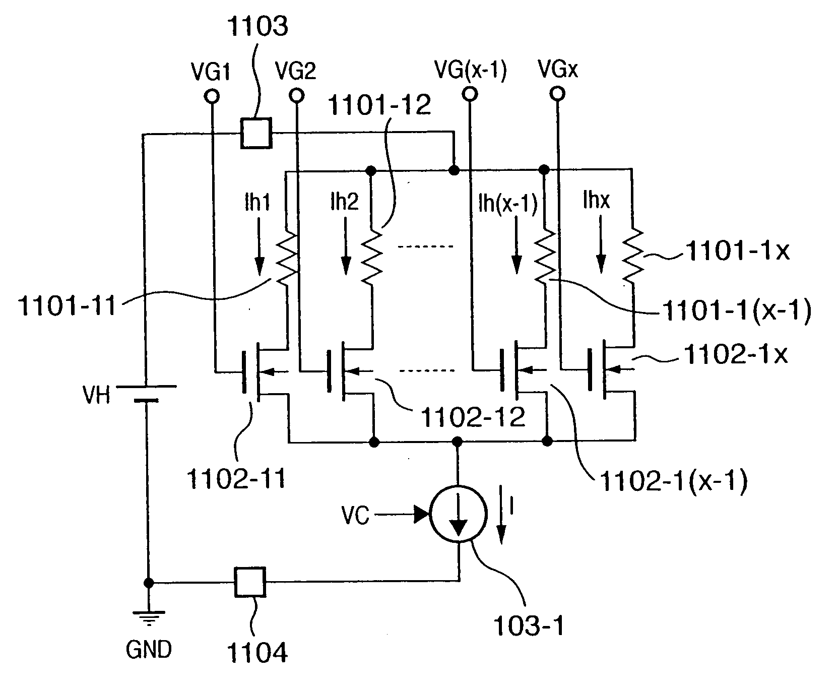
[0116]FIG. 8 is an example of a layout for illustrating an actual arrangement of elements, such as the heaters, transistors, control circuits, and constant electric current sources, in the heater driving circuit (equivalent circuit) shown in FIG. 5. Also in FIG. 8, the same reference numerals as those in FIG. 5 denote areas where the corresponding building components are arranged. Note that the head substrate according to the present invention is a rectangular substrate with longer sides and shorter sides. Heaters and transistors for switching are arrayed along with the longer side direction (longitudinal direction).

[0117] For example, in a group 1100-1, a heater group and transistor group respectively including heaters 1101-11 to 1101-1x and MOS transistors 1102-11 to 1102-1x are formed. Likewise, in a group 1100-m, a heater group and transistor group respectiv...

second embodiment

[0130]FIG. 10 is a view showing the layout of a head substrate according to the second embodiment of the present invention.

[0131]FIG. 10 illustrates an example of a layout which implements the heater driving circuit shown in FIG. 5. FIG. 11 is a view showing the layout of power supply lines on the head substrate shown in FIG. 5.

[0132] Note that, in FIGS. 10-11, the same reference numerals as those in FIGS. 5, 8 and 9 denote the same building components.

[0133] As is apparent from a comparison between FIGS. 8 and 9 described in the first embodiment and FIGS. 10 and 11 in this embodiment, the arrangement of a constant electric current source group 103 is centralized at the center of the board, and the arrangement interval is set smaller than that of the array of a heater group 1101.

[0134] According to this embodiment, the distance between constant electric current sources is shortened, and the relative electric current error of an electric current output from each constant electric...

third embodiment

[0135]FIG. 12 is a view showing the layout of a head substrate according to the third embodiment of the present invention.

[0136]FIG. 13 illustrates an example of a layout which implements the heater driving circuit shown in FIG. 5. FIG. 13 is a view showing the layout of power supply lines on the head substrate shown in FIG. 12.

[0137] Also in FIGS. 12 and 13, the same reference numerals as those in FIGS. 5, 8, and 9 denote the same building components.

[0138] As is apparent from a comparison between FIGS. 8 and 9 described in the first embodiment and FIGS. 12 and 13 in this embodiment, constant electric current sources 103-1 to 103-m which constitute a constant electric current source group 103 are interposed between input / output pads 106 and 107.

[0139] The inkjet printhead considered in the present invention achieves high-speed printing by arranging heaters as many as possible and increasing the number of concurrently driven heaters. For this purpose, the heater substrate is elo...


PUM


Abstract

An object of this invention is to provide a driving circuit layout which suppresses an increase in the area of a head substrate in an inkjet printhead adopting a driving method for supplying a predetermined current to a heater. To achieve this object, a plurality of printing elements and a plurality of switching elements which are very large in number are arrayed in the longitudinal direction of a head substrate. A plurality of terminals which receive a driving signal and a control signal that are used to drive the plurality of printing elements are arranged at the end of the board in the longitudinal direction of the board at positions opposite to the array of the plurality of printing elements. A constant electric current source for supplying a predetermined electric current is interposed between these two regions.

Description

FIELD OF THE INVENTION [0001] This invention relates to a printhead substrate, printhead, head cartridge, and printing apparatus and, more particularly, to a printhead substrate, containing a circuit for driving a printing element by sending a predetermined electric current, which is used to print in accordance with an inkjet method, printhead, head cartridge, and printing apparatus. BACKGROUND OF THE INVENTION [0002] An inkjet printhead (to be referred to as a printhead hereinafter), which generates thermal energy by sending an electric current to a heater arranged in the nozzle so as to discharges ink, has conventionally been known. [0003] This printhead is a printhead which employs a method of bubbling ink near the heater by using the generated thermal energy, and discharging ink from the nozzle to print. [0004] In order to print at a high speed, heaters (printing elements) mounted in a printhead are desirably concurrently driven as many as possible to discharge ink at the same t...

Claims


Application Information

Patent Timeline
Patent Type & Authority Applications(United States)
IPC IPC(8): B41J2/05B41J2/14B41J2/205
CPCB41J2/0458B41J2/04541B41J2002/043B41J2/05
Inventor HIRAYAMA, NOBUYUKI
Owner CANON KK
Why Eureka
Try Eureka