Liquid crystal display panel

Inactive Publication Date: 2005-12-01
JAPAN DISPLAY CENT INC
View PDF6 Cites 7 Cited by
  • Summary
  • Abstract
  • Description
  • Claims
  • Application Information

AI Technical Summary

Benefits of technology

[0013] It is an object of the present invention to provide an OCB mode liquid crystal display panel that can suppress non-uniformity in display caused by impurity ions when black insertion driving is carried out in a display operation. According to the invention, there is provided an OCB mode liquid crystal display panel, which comprises: a pair of electrode substrates; a liquid crystal layer which is held between the pair of electrode substrates and h

Problems solved by technology

Such impurity ions decrease the insulation resistance of the liquid crystal.
Thus, the display characteristics are impaired due to decreased voltage retention.
When the impurity ions are distributed unevenly, an image fault such as non-uniformity in display occurs.
However, it is difficult to use this technique as a solution to the problem occurring in the OCB mode l

Method used


Image

  • Liquid crystal display panel
  • Liquid crystal display panel
  • Liquid crystal display panel

Examples


Embodiment Construction

[0024] An OCB mode liquid crystal display panel LCD according to one embodiment of the present invention will be described with reference to the accompanying drawings.

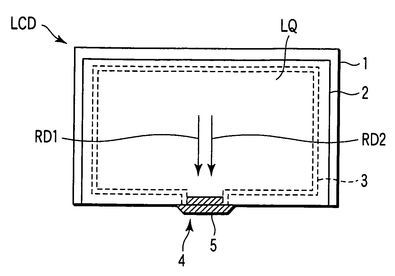
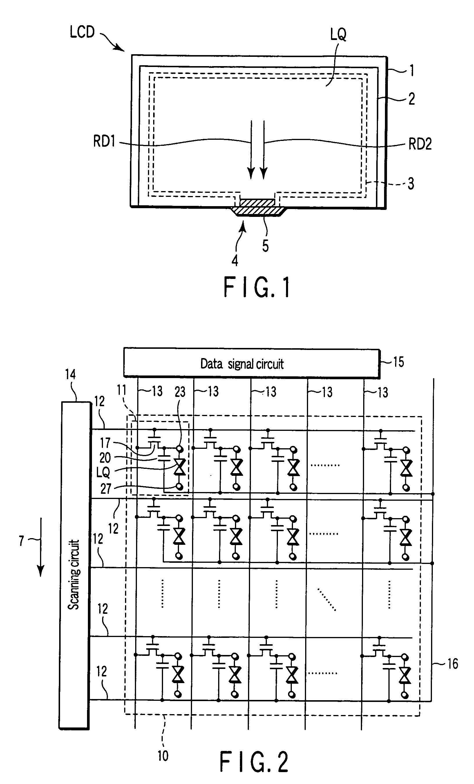
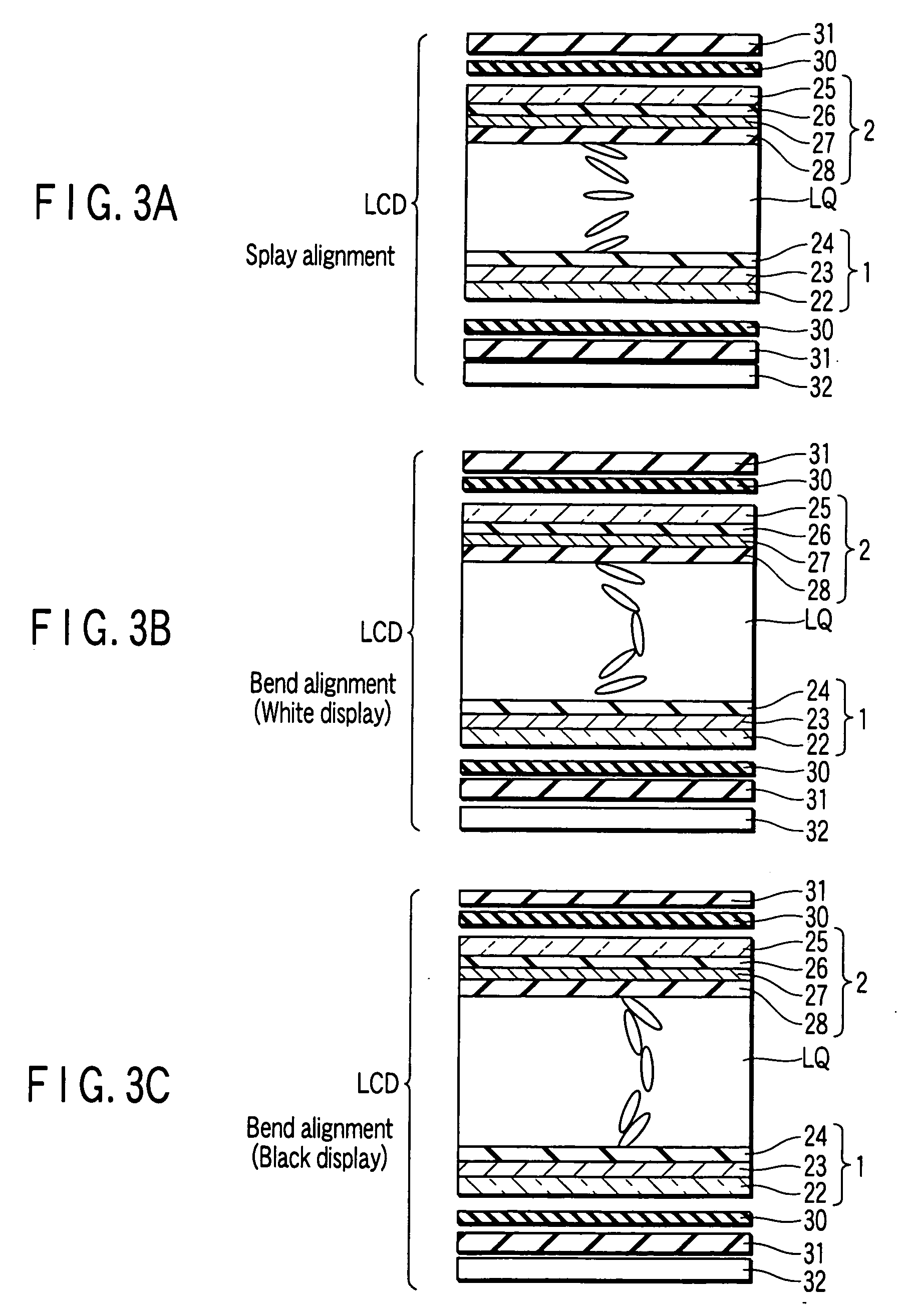
[0025]FIG. 1 shows the plane structure of the liquid crystal display panel LCD, FIG. 2 schematically shows the circuit configuration of the liquid crystal display panel LCD, FIGS. 3A to 3C shows the cross sectional structure of the liquid crystal display panel LCD. As shown in FIG. 1, the liquid crystal display panel LCD includes an array substrate 1, a counter substrate 2, and a liquid crystal layer LQ held between the array substrate 1 and the counter substrate 2. The array substrate 1 and counter substrate 2 are a pair of electrode substrates each of which is a rectangular, and bonded by use of a sealing resin layer 3, which is applied to surround a liquid crystal filling space between the substrates 1 and 2 and form an open part left as an inlet 4. The liquid crystal layer LQ is obtained by filling the liquid crys...


PUM


Abstract

An OCB mode liquid crystal display panel comprises a pair of electrode substrates, a liquid crystal layer which is held between the pair of electrode substrates and has liquid crystal molecules whose alignment state is controlled within a display area by a drive voltage applied from the electrode substrates, and a pair of alignment films which are disposed on the electrode substrates in contact with the liquid crystal layer and whose rubbing directions are set parallel to each other. The rubbing directions of the pair of alignment films are oriented toward a side of a main diffusion source of impurity ions.

Description

CROSS-REFERENCE TO RELATED APPLICATIONS [0001] This application is based upon and claims the benefit of priority from the prior Japanese Patent Application No. 2004-159657, filed May 28, 2004, the entire contents of which are incorporated herein by reference. BACKGROUND OF THE INVENTION [0002] 1. Field of the Invention [0003] The present invention relates to a liquid crystal display panel having an optically compensated bend (OCB) mode. [0004] 2. Description of the Related Art [0005] Liquid crystal display panels have widely been used as image displays for computers, automobile navigation systems, monitors and TVs. TN and STN modes using nematic liquid crystals are popular as liquid crystal display modes for the liquid crystal display panels. Other liquid crystal display modes using ferroelectric liquid crystals and the like are also known and provide a higher response speed and a wider viewing angle. These display modes, however, require further improvement in impact resistance and...

Claims


Application Information

Patent Timeline
IPC IPC(8): G02F1/133G02F1/1335G02F1/1337G02F1/139
CPCG02F1/1395G02F1/1337
Inventor NAKAO, KENJIOGAWA, SHINJIWAKEMOTO, HIROFUMI
Owner JAPAN DISPLAY CENT INC
Why Eureka
Try Eureka