Optical modulator, optical modulator manufacturing method, light information processing apparatus including optical modulator, image formation apparatus including optical modulator, and image projection and display apparatus including optical modulator

a light information processing and manufacturing method technology, applied in the field of light modulators, can solve the problems of low stability of cantilever, inability to disadvantageously accelerate response speed, signal response deterioration, etc., and achieve the effects of stable operation, simple modulation of light, and fast respons

Inactive Publication Date: 2005-12-01
RICOH KK
View PDF12 Cites 14 Cited by
  • Summary
  • Abstract
  • Description
  • Claims
  • Application Information

AI Technical Summary

Benefits of technology

[0013] It is an object of the present invention to provide a light modulator, a method of manufacturing a light modulator, a light information processing apparatus which includes the light modulator, an image formation apparatus which includes the light modulator and an image projection and display apparatus which includes the light modulator wherein a structure of changing the reflection direction of incident light to be used and thereby modulating light is simple, response is fast, the wavelength of the incident light is not limited, stable operation is ensured, reliability is high, the number of manufacturing steps is small and manufacturing yield is high.
[0015] According to this aspect, the light modulator consists of the substrate in which the concave section is formed, the substrate electrode which is formed on the inner surface of the concave section, the thin film type center beam which is provided at the position opposed to the substrate electrode through the gap in the concave section and the both ends of which are fixed, and the light reflection film and the beam electrode which are formed on the upper surface of the center beam. The concave section is formed so that the center beam which is deformed by applying a driving voltage to the substrate electrode and the beam electrode is abutted on the inner surface of the concave section, to thereby restrict the deformation of the center beam.
[0016] According to another aspect of the present invention, there is provided a light modulator modulating light by changing a reflection direction of incident light, comprising: a reflection unit which regularly reflects light; a thin film, both-end-fixed beam which is formed out of a thin film constituted to be combined with the reflection unit provided on one side surface of the thin film, both-end-fixed beam, which has both ends fixed, and which is deformed by an electronic force; a substrate electrode which is opposed to the thin film, both-end-fixed beam, and which applies a driving voltage; a gap which is formed by opposing the substrate electrode to the thin film, both-end-fixed beam, and which is formed on the other side surface of the thin film, both-end-fixed beam; a substrate which has the substrate electrode formed on a bottom of the gap, formed in a concave section and which holds and fixes the both ends of the thin film, both-end-fixed beam; and a hole section which is formed in the thin film, both-end-fixed beam above the gap, and which makes a section of the thin film, both-end-fixed beam corresponding to the hole section deformed more easily than remaining sections of the hole section.

Problems solved by technology

For these reasons, the cantilever has low stability.
Furthermore, in case of the cantilever, signal response is deteriorated due to the free oscillation thereof.
Therefore, it is disadvantageously difficult to ensure the stability of the cantilever and the natural frequency of the cantilever is low, with the result that the response speed cannot be disadvantageously accelerated.
However, since the structure of the device is too complicated, it is difficult to improve yield.
In addition, since the mirror is held by the thin torsion bar, the service life of the device cannot be lengthened.
However, the device which drives a diffraction grating by an electrostatic force and switches light, has a disadvantage in that the wavelength of incident light to be used is limited.
However, with the device which bends a beam by an electrostatic force, adjusts the focus of reflection light and passes the reflection light through a slit to thereby switch light, the bending degree of the beam becomes often unstable, disadvantageously deteriorating the reliability of the device.
As explained above, the conventional light modulators each of which modulates light by changing the reflection direction of an incident light beam, a light information processing apparatus which includes the conventional light modulator, an image formation apparatus which includes the conventional light modulator and an image projection and display apparatus which includes the conventional light modulator have disadvantages in that the structure of changing the reflection direction of an incident light beam and thereby modulating light is complex, response is slow, the wavelength of the incident light to be used is limited, operation is unstable and reliability deteriorates.

Method used


Image

  • Optical modulator, optical modulator manufacturing method, light information processing apparatus including optical modulator, image formation apparatus including optical modulator, and image projection and display apparatus including optical modulator
  • Optical modulator, optical modulator manufacturing method, light information processing apparatus including optical modulator, image formation apparatus including optical modulator, and image projection and display apparatus including optical modulator
  • Optical modulator, optical modulator manufacturing method, light information processing apparatus including optical modulator, image formation apparatus including optical modulator, and image projection and display apparatus including optical modulator

Examples


first embodiment

[0195] A first embodiment will be explained in detail with reference to FIGS. 1 to 80.

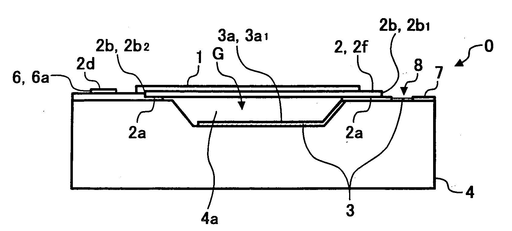
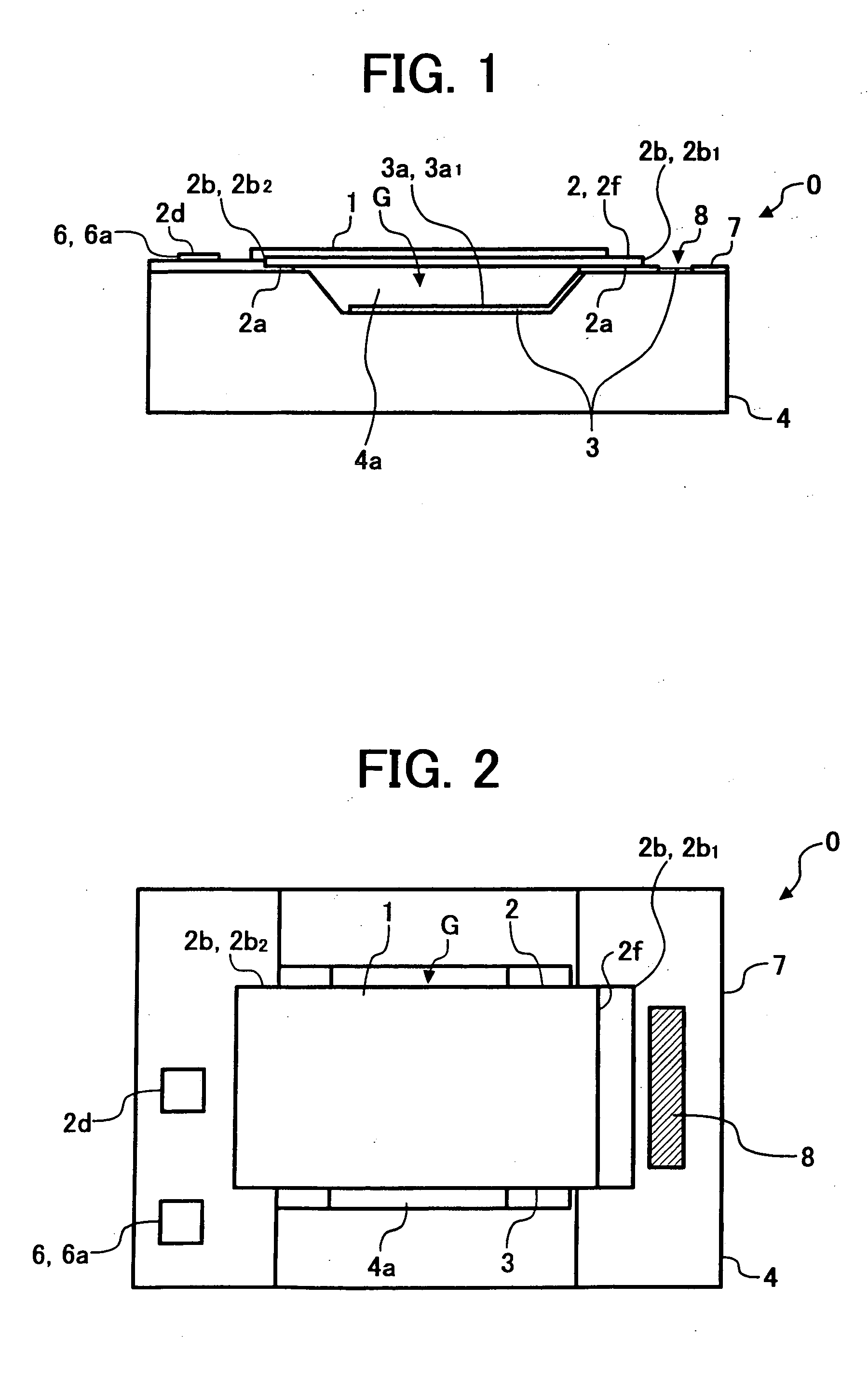
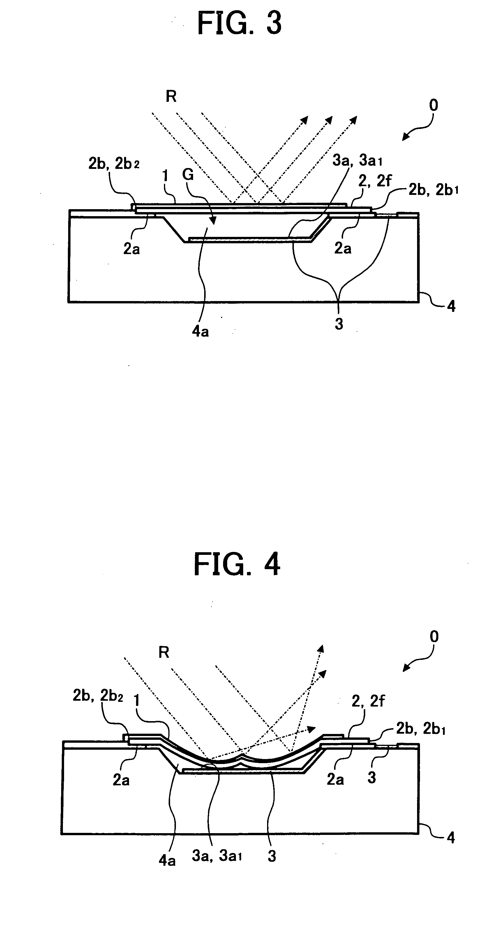
[0196] In FIGS. 1 and 2, a light modulator 0 which modulates light by changing the reflection direction of incident light, consists of a light reflection film 1, a center beam 2, a substrate electrode 3 and a substrate 4. The light reflection film 1 regularly reflects the incident light. The center beam 2 is formed out of a thin film constituted to be combined with the light reflection film 1 formed out of a metallic thin film on the front side of one surface of the center beam 2. The both ends of the center beam 2 are fixed and the center beam 2 is deformed by an electrostatic force. The substrate electrode 3 is opposed to the center beam 2 across a gap (G) in a concave section 4a formed on the rear side of the other surface of the center beam 2 constituted to be combined with a beam electrode 2f so that a voltage can be applied to the center beam 2. The substrate electrode 3 applies a driving vo...

second embodiment

[0354] A second embodiment will be explained hereinafter with reference to FIGS. 81 to 105.

[0355]FIGS. 81A and 81B are a longitudinal sectional view and a plan view which shows the configuration of a light modulator according to the second embodiment, respectively. In FIGS. 81A and 81B, a light modulator 1000 which modulates light by changing the reflection direction of incident light consists of a reflection unit 1001, a thin film, both-end-fixed beam (center beam) 1002, a substrate electrode 1003, a gap 1004, a substrate 1005 and a hole section 1006. The reflection unit 1001 regularly reflects the incident light. The thin film, both-end-fixed beam (center beam) 1002 is constituted to be combined with the reflection unit 1001 provided on a side surface thereof (an upper surface in FIGS. 81A and 81B) and formed out of a thin film. The both ends of the thin film, both-end-fixed beam (center beam) 1002 are fixed and the thin film, both-end-fixed beam (center beam) 1002 is deformed by...

third embodiment

[0462] A third embodiment will be explained hereinafter in the order of [First example of Third embodiment] and [Second example of Third embodiment] with reference to FIGS. 106 to 126.


PUM


Abstract

A center beam which is formed out of a thin film constituted to be combined with a light reflection film provided on one surface of the center beam, which has both ends fixed and which is deformed by an electronic force; a substrate electrode which is opposed to the center beam through a gap formed on the other surface of the center beam; an opposed surface which is a surface of the substrate electrode opposed to the center beam modulating the incident light on the light reflection film, the opposed surface restricting deformation of the center beam due to application of a driving voltage to the substrate electrode by abutting on the center beam; and a substrate which has the substrate electrode having the opposed surface, formed in a concave section, and which holds a to-be-held section of the center beam, are provided. As a result, the structure of modulating light by changing the reflection direction of the incident light is simple, response is fast, the wavelength of the incident light to be used is not limited, operation is stable, reliability is high, the number of manufacturing steps is small and cost reduction can be achieved.

Description

FIELD OF THE INVENTION [0001] The present invention relates to a light modulator, a light modulator manufacturing method, a light information processing apparatus including the light modulator, an image formation apparatus including the light modulator and an image projection and display apparatus including the light modulator. More particularly, the present invention relates to a light modulator which modulates light by changing the reflection direction of incident light, a method of manufacturing the light modulator, an light information processing apparatus which includes the light modulator and performs an light information processing using the light modulator which performs light modulation by changing the reflection direction of incident light, an image formation apparatus which includes the light modulator and forms an image by writing optical data by an electrophotographic process, and an image projection and display apparatus which includes the light modulator and projects ...

Claims


Application Information

Patent Timeline
Patent Type & Authority Applications(United States)
IPC IPC(8): G02B26/02
CPCG02B26/02
Inventor OHTAKA, KOUICHIKATOH, SEIICHINANJYO, TAKESHIHORIKE, MASANORIOHTA, EIICHI
Owner RICOH KK
Why Eureka
Try Eureka