Compact fluorescent lamp and luminaire using the same

a fluorescent lamp and compact technology, applied in the direction of fixed installation, sustainable buildings, light and heating apparatus, etc., can solve the problems of excessive rise in mercury vapor pressure in the fluorescent tube, affecting the efficiency of heat dissipation of fluorescent tubes, and reducing the heat dissipation efficiency of fluorescent tubes, so as to improve the delay of light flux rise-up, the effect of enhancing the light flux rise-up characteristi

Inactive Publication Date: 2005-12-01
TOSHIBA LIGHTING & TECH CORP
View PDF18 Cites 38 Cited by
  • Summary
  • Abstract
  • Description
  • Claims
  • Application Information

AI Technical Summary

Benefits of technology

[0018] In compact fluorescent lamps, inside the envelope is tend to become relatively high temperature, since the lighting device and the fluorescent tube are encapsulated in a narrow envelope, due to the heat radiated from the fluorescent tube. Accordingly, even if a portion of the thin tube is protruding to the vicinity of the cap and resides very far from the fluorescent tube, the portion is easily affected by the heat due to that the thin tube is physically connected to the fluorescent tube.
[0073] According to this aspect of the compact fluorescent lamp, although the main amalgam is placed in remote position from the fluorescent tube, the composition of the auxiliary amalgam is optimized. So that, the decreasing of light flux due to the shortage of mercury just after the lighting start is depressed, and the light flux rise-up characteristic can be enhanced certainly.

Problems solved by technology

However, there is a tendency that a heat dissipation efficiency of fluorescent tubes falls down and thus the temperature thereof rises up, along with the downsizing thereof.
When fluorescent-tube encapsulating mercury therein is heated to high temperature, a mercury vapor pressure in the fluorescent tube rises excessively, and its light output falls.
However, Prior art C has a drawback that in case of the fluorescent tube being enclosed in a glove, the temperature of the cool spot fails to fall to a desired temperature, since the heat generated by the So, a cool spot with a desired temperature can be induced on the thin tube by dividing the inside of an envelope containing the glove into a can be divided into a fluorescent tube compartment and a lighting device compartment with a partition, and then protruding the thin tube from the tube end into the lighting device compartment by 5-20 mm long.
However, even a fluorescent lamp equipped with auxiliary amalgam is difficult to raise promptly the mercury vapor pressure just after a lighting start, and to assure a desired lightness.
In a globe-less compact fluorescent lamp, even if a cool spot is inducing on a portion of the fluorescent tube, there is a case that the cool spot fails to become a sufficient low temperature depending to its posture.
Therefore, it takes a long time until the lamp gets warm to the temperature for releasing the mercury vapor from the cool spot by which mercury vapor is emitted from a cool spot at a re-lighting.

Method used


Image

  • Compact fluorescent lamp and luminaire using the same
  • Compact fluorescent lamp and luminaire using the same
  • Compact fluorescent lamp and luminaire using the same

Examples


first embodiment

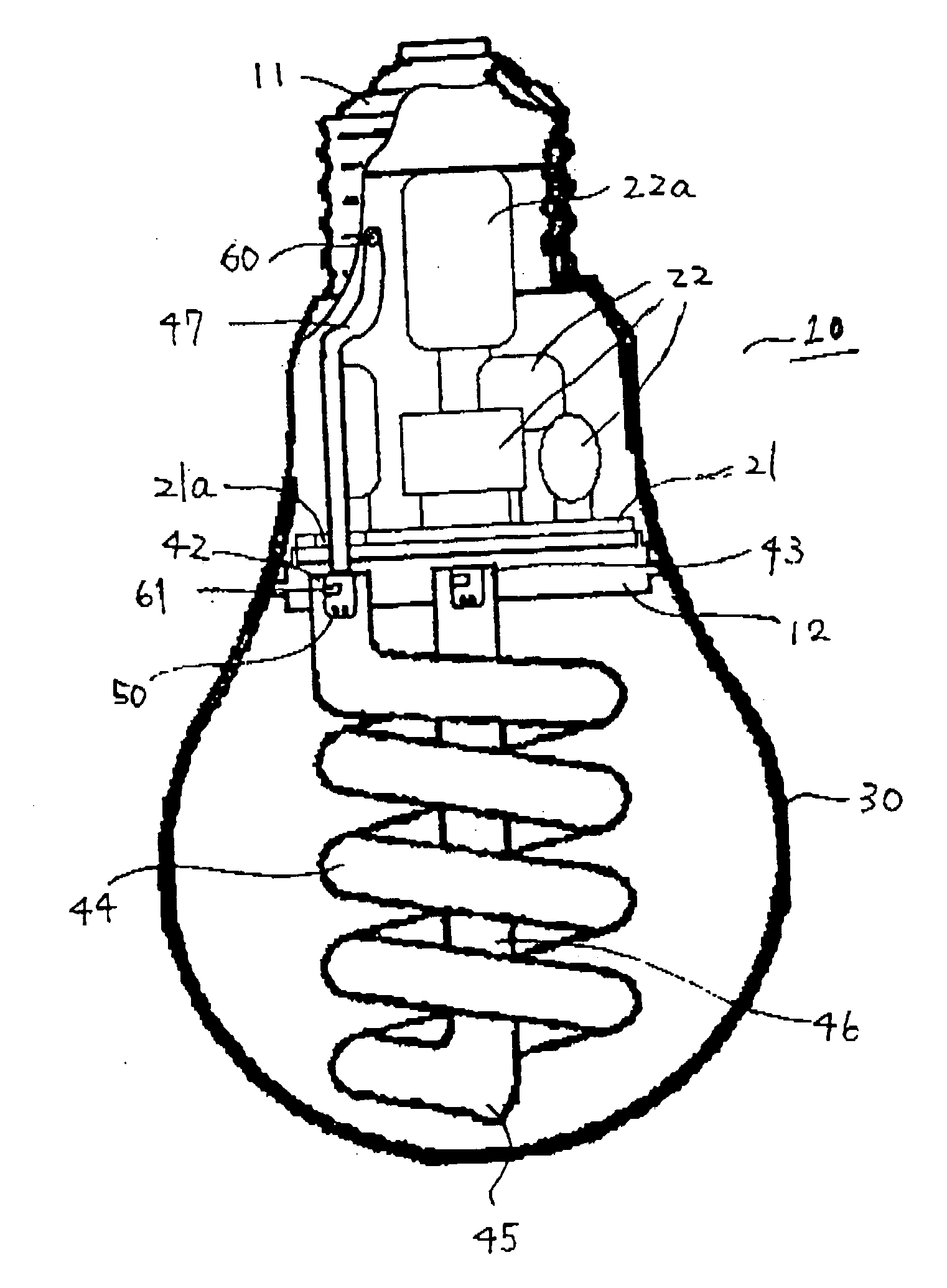
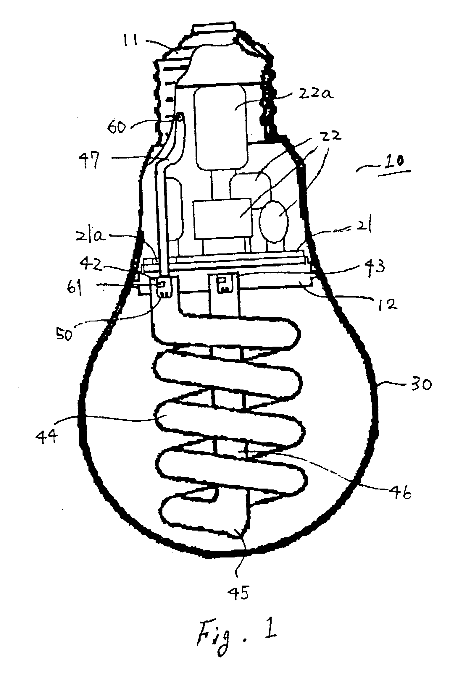
[0089]FIG. 1 shows a compact fluorescent lamp.

[0090] As shown in FIG. 1, compact fluorescent lamp 10 is equipped with a fluorescent tube 40, a lighting device 20, a holder 11, a cap 11, and a glove 30. The glove 30, the holder 12 and the cap 11 constitute an envelope 15. The envelope 15 is shaped in a profile approximating to that of ordinary incandescent lamps with 60 W rated-powers. Here, the term “ordinary incandescent lamp” is defined in “JISC7501”. The length of the compact fluorescent lamp 10, i.e., the size of the envelope 15 from the head of the cap 11 to the head of the glove 30, is 110-125 mm. The maximum diameter of the compact fluorescent lamp 10, i.e., the diameter of the glove 30, is 50-60 mm. Here, the diameter of the holder 12 is formed in broadly around 40 mm.

[0091] On the inner surface of fluorescent tube 40, a protective film (not shown) made of alumina is applied, and further a fluorescent substance layer (not shown) is applied on the protective film. The fluore...

second embodiment

[0129] Referring now to FIG. 3, the present invention will be explained.

[0130]FIG. 3 is a partial sectional front view showing the second embodiment of the compact fluorescent lamp. Here, the same reference numerals are added to the same or corresponding portions as of the first embodiment shown in FIG. 1, and the detailed explanation is omitted.

[0131] In the second embodiment, a pellet type zinc amalgam containing the mercury below 10 mg is enclosed in the fluorescent tube 40 in place of the main amalgam.

[0132] The fluorescent tube 40 constitutes a helical fluorescent tube wherein a straight glass tube is folded at the turning portion 45 around its central portion, and the entire of both sides arranged in parallel are constituted in a double-helical fluorescent tube by being helically revolved in the same direction. And a thin tube 47 helically protrudes from one of the tube ends 42 along the line of the corresponding one of the helical fluorescent tubes.

[0133] The tube end 42 o...

third embodiment

[0150] In this third embodiment, the main amalgam 60 is placed in the tip end of the thin tube 47, and the tip end of the thin tube 47 is adhered to the inner surface of the cap 11 by using a silicone adhesive 51. A cutout 14 is defined around the neck 13 of the holder 12 to be mounted with the cap 11, and then the tip end of the thin tube 47 is adhered to the inner surface of the cap 11.

[0151] In this third embodiment, the tip end of the thin tube 47 and if necessary the circuit elements such as the electrolytic capacitor located in the vicinity of the tip end of the thin tube are preliminarily applied the silicone adhesive, and then mechanically and thermally coupled to the cap 11 by the silicone adhesive at the time that the cap 11 is attached to the holder 12

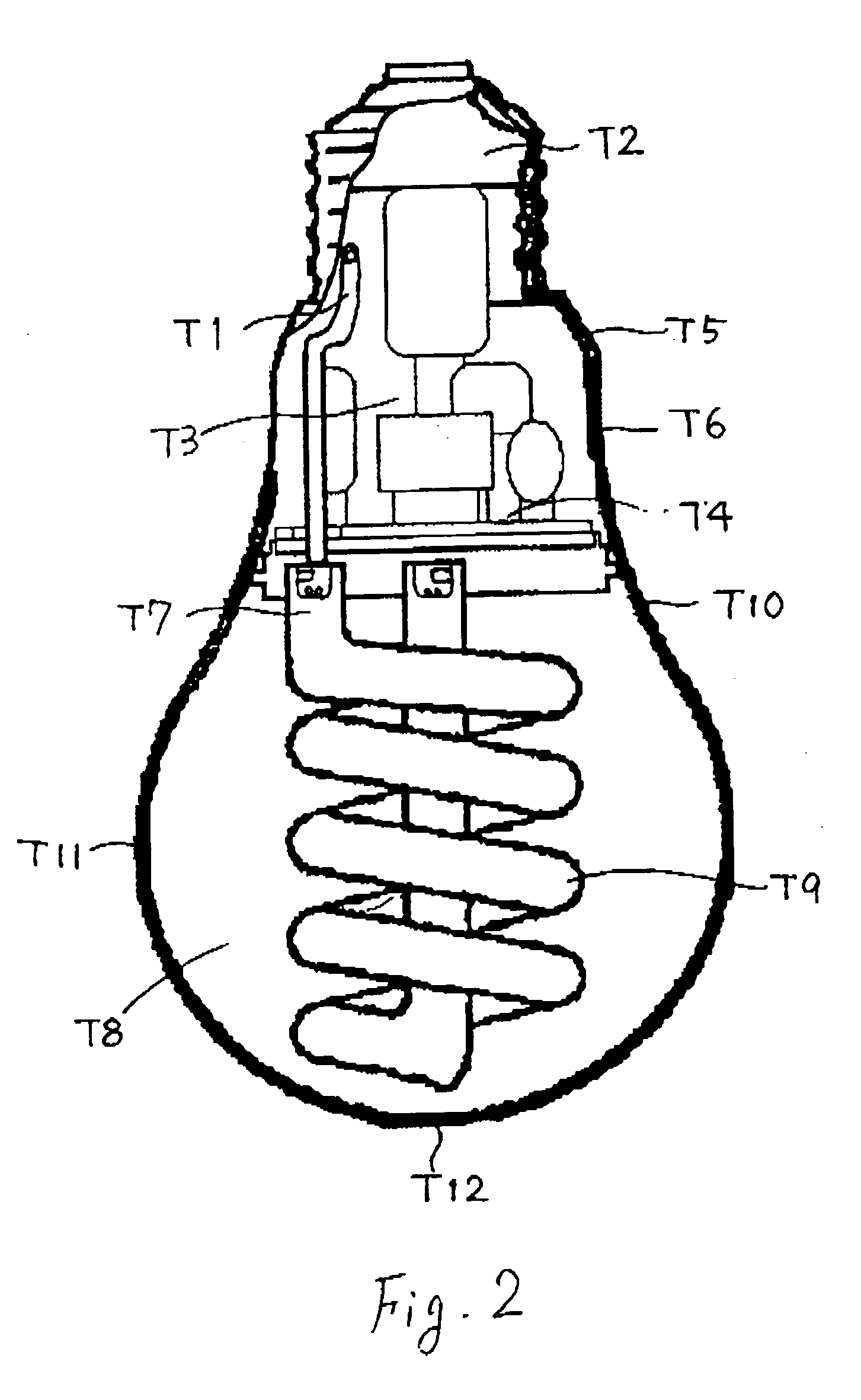
[0152] Now, a result of measuring temperatures in the compact fluorescent lamp having the fluorescent tube as shown in FIG. 4e will be explained. The measurement was performed in the case that the tip end of the thin tube 47...


PUM


Abstract

A compact fluorescent lamp comprises a fluorescent tube having a helical portion on at least a part thereof and turned down in the middle, a pair of tube ends thereof each provided with a discharge electrode, the pair of tube ends juxtaposing with each other in the same direction, a holder for holding the tube ends so as that the fluorescent tube is supported at the one side thereof, a lighting device for supplying a high-frequency power to the fluorescent tube, the lighting device comprising a circuit board facing the other side of the holder and circuit elements mounted on the circuit board, a cover for accommodating the lighting device the cover opening at both ends and holding the holder at the one opening end, and a cap fixed to the other opening end of the cover for supplying a commercial power to the lighting device by being mounted to a socket of luminaire, wherein a thin tube is protruded from at least one of the tube ends of the fluorescent tube in the cover, and the thin tube is communicated with the fluorescent tube.

Description

CROSS-REFERENCE TO RELATED APPLICATIONS [0001] This application is based upon and claims the benefit of priority from the prior Japanese Patent Application JP2004-138568 filed on May 7, 2004, the entire content of which is incorporated herein by reference. FIELD OF THE INVENTION [0002] This invention relates to a compact fluorescent lamp and luminaire using the same. BACKGROUND OF THE INVENTION [0003] In recent years, compact fluorescent lamps have been downsized in comparable to ordinary incandescent lamps, and invite an increasing replacement demand from such incandescent lamps. [0004] As an example of such a compact fluorescent lamp, Japanese patent application Tokkai 2000-228169 (prior art A) discloses those wherein a fluorescent tube is helically packed. [0005] However, there is a tendency that a heat dissipation efficiency of fluorescent tubes falls down and thus the temperature thereof rises up, along with the downsizing thereof. Such a tendency is especially remarkable in a ...

Claims


Application Information

Patent Timeline
Patent Type & Authority Applications(United States)
IPC IPC(8): F21S8/00H01J61/00H01J61/20H01J61/28H01J61/32H01J61/34
CPCH01J61/20H01J61/28Y02B20/19H01J61/34H01J61/327Y02B20/00
Inventor YASUDA, TAKEOIKADA, KUNIHIKO
Owner TOSHIBA LIGHTING & TECH CORP
Why Eureka
Try Eureka