
Processing of medical signals

Active Publication Date: 2005-12-01
FUJIFILM SONOSITE
View PDF33 Cites 137 Cited by
  • Summary
  • Abstract
  • Description
  • Claims
  • Application Information

AI Technical Summary

Benefits of technology

[0007] The present invention is directed to a system and method in which real-time ubiquitous imaging is feasible in local areas, such as inside a clinic, hospital room or doctor office. This is achieved by designing a wireless network having a central processing server with, for example, distributed broadband acquisition and video bus capability. Remote access is possible using store-and-forward image transfer over a wide area network. With these capabilities, a physician can use a handheld transducer (such as an ultrasound transducer) as a basic tool to facilitate diagnostic decisions similar to the way a stethoscope is used today.
[0008] In one embodiment, a handheld ultrasound imaging system is constructed similar in size to a cellular handset. The imaging system has wireless connectivity, using, for example, a low cost CMOS process for implementing imaging functions with signal processors. This enables medically relevant information to be accessible by the handheld ultrasound device and also allows images acquired from the handheld device to be transferred and retrieved from a number of locations while the signals are processed from a location common to all of those locations.

Problems solved by technology

Such systems however, typically have limited network connectivity and storage and generally lack the capability of accessing patient files or other relevant medical information that reside within a hospital information system.
As any new technology or application evolves, new operational issues and demands from users arise.
Some of these issues are: image quality, user interface, display size, battery power, packaging, system size and weight, transducer size and weight, image analysis and connectivity.
The requirement of high performance, however, typically increases the complexity of system design and is generally in conflict with the requirement of smaller system size necessary for mobility.
However, by doing so this will also result in possible undesirable reduction of clinically efficacy.

Method used


Image

  • Processing of medical signals
  • Processing of medical signals
  • Processing of medical signals

Examples


Embodiment Construction

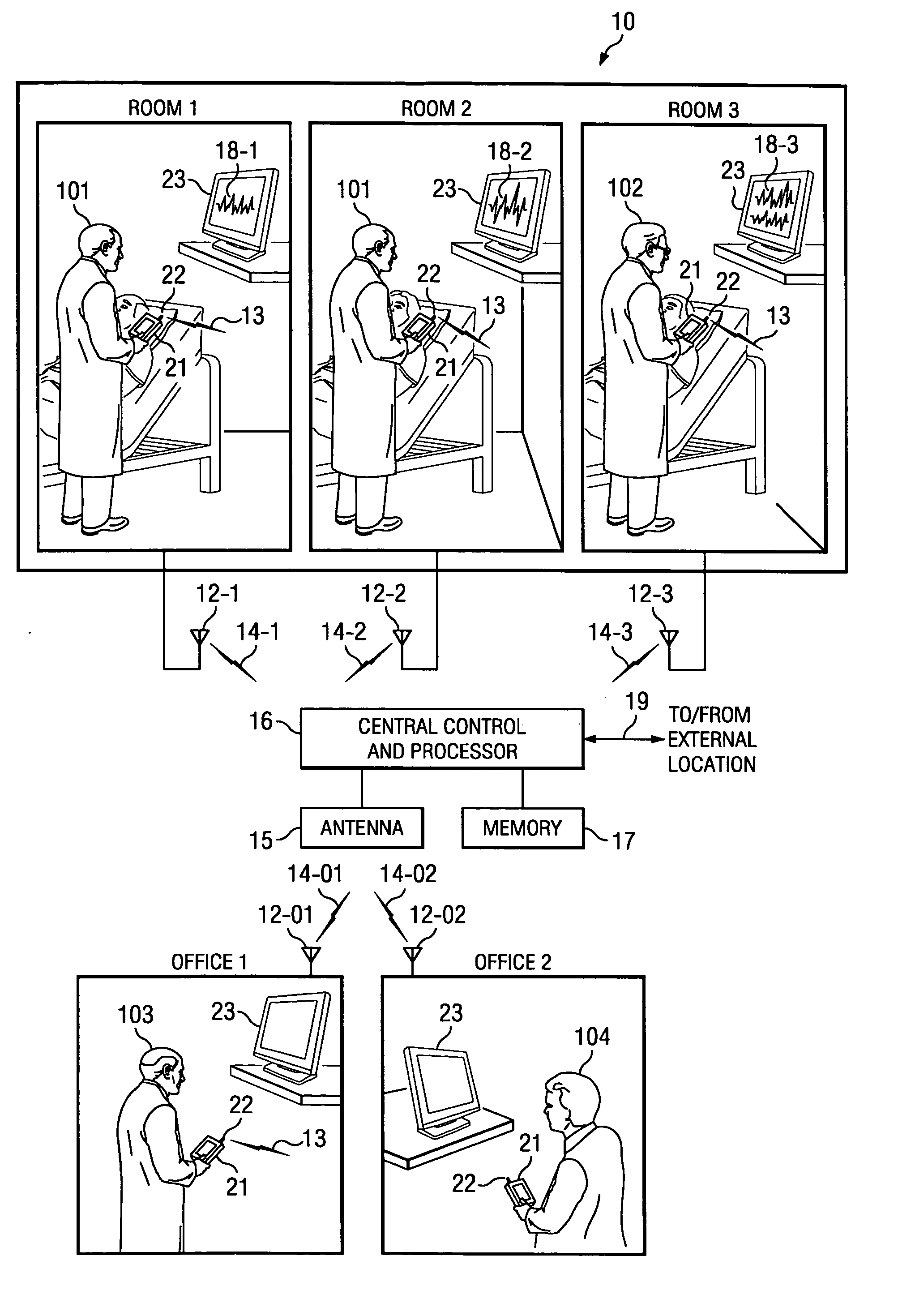
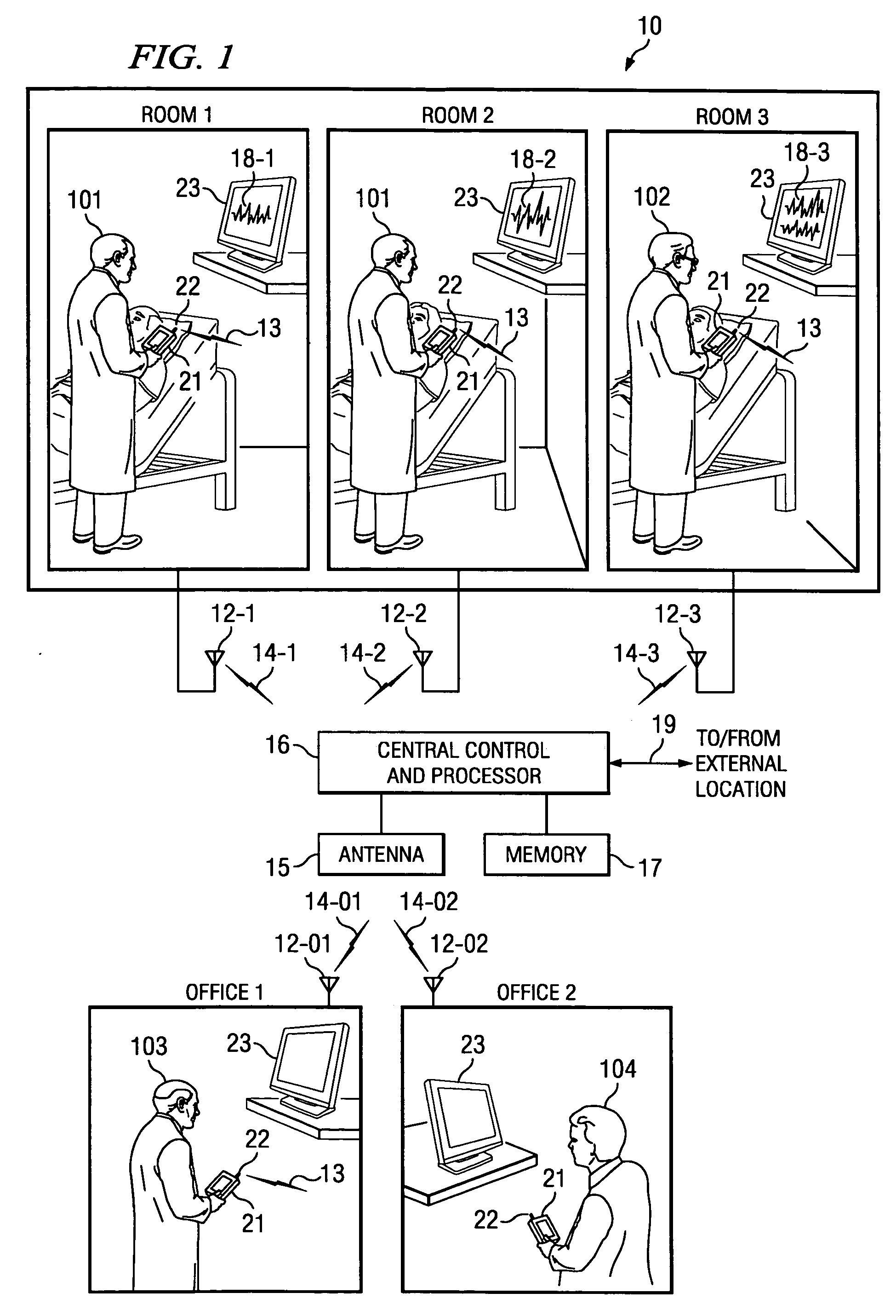
[0016]FIG. 1 shows one embodiment 10 of a ubiquitous system having a high performance back-end processing server, such as a central control and processor 16. Processor 16 is used in conjunction with transducer devices, such as devices 21, which can move from room to room or from office to office as one or more physicians (101-104) moves about. Signals 13 to and from each device 21 are transmitted, for example, via antenna 22 (room 1) to trans / receiver 12-1 and to / from trans receiver 12-1 and server 16 via antenna 15 and transmission path 14-1. Transmission path 14-1 can be wireless or wireline or a combination thereof. Also, receiver (radio access point) 12-1 can serve a plurality of rooms or locations or could serve a particular room, as shown by (12-1, 12-2, 12-3, 12-01, 12-02).

[0017] The processing power of process 16 (which acts as a server) is designed to be capable of simultaneously processing data received from multiple radio access points. In return, if desired, processed s...


PUM


Abstract

The present invention is directed to a system and method in which real-time ubiquitous imaging is feasible in local areas, such as inside a clinic, hospital room or doctor office. This is achieved by designing a wireless network having a central processing server with, for example, distributed broadband acquisition and video bus capability. Remote access is possible using store-and-forward image transfer over a wide area network. With these capabilities, a physician can use a handheld transducer (such as an ultrasound transducer) as a basic tool to facilitate diagnostic decisions similar to the way a stethoscope is used today.

Description

CROSS REFERENCE TO RELATED APPLICATIONS AND PATENTS [0001] The present application is related to co-pending, and commonly-assigned U.S. patent application Ser. No. 10 / 821,123, Attorney Docket No. 65744 / P018US / 10404217, entitled “Systems And Methods Providing ASICS For Use In Multiple Applications,” filed Apr. 8, 2004 and U.S. patent application Ser. No. 10 / 821,198, Attorney Docket No. 65744 / P021US / 10404749, entitled “System And Method For Enhancing Gray Scale Output On A Color Display,” filed Apr. 8, 2004; the disclosures of which are all hereby incorporated herein by reference herein.TECHNICAL FIELD [0002] The embodiments of this disclosure are directed to medical diagnostic and / or treatment systems and more particularly to systems and methods for the ubiquitous processing of medical signals originating from medical equipment at diverse locations. BACKGROUND OF THE INVENTION [0003] Similar to the development of PCs in computing and cellular telephones in mobile communication, syste...

Claims


Application Information

Patent Timeline
IPC IPC(8): G16H30/20G16H40/63H04B7/00
CPCG06F19/321G06F19/3418G06Q50/24G06F19/3481G06Q50/22G06F19/3425G16H80/00G16H30/20G16H40/63
Inventor HWANG, JUINJET
Owner FUJIFILM SONOSITE
Learn More