
Spheric alignment mechanism

a technology of spheric alignment and superconducting shell, which is applied in the direction of superconducting magnets/coils, magnetic bodies, nuclear elements, etc., can solve the problems of failure to disclose or suggest, and prior devices cannot provide an entropically isolated environment for work products within such devices

Active Publication Date: 2005-12-01
KESSLER STEPHEN BURNS
View PDF13 Cites 18 Cited by
  • Summary
  • Abstract
  • Description
  • Claims
  • Application Information

AI Technical Summary

Benefits of technology

[0008] The present invention effects zero point energy on atomic strong / weak force and molecular structures by creating an entropically isolated environment in which ambient electromagnetic fields are minimized during the critical initiating phase of energetic conversion of zero point energy. More particularly, the chamber of the present invention maintains a mixed state of low entropy followed by high entropy and effects atomic and molecular structures of the work product placed within the chamber. Accordingly, the chamber can be used in biophysics / life sciences, electronics, computer science, energy production, particle physics, electromagnetism, chemistry, pharmaceuticals and materials production.

Problems solved by technology

However, these prior devices fail to disclose or suggest a superconducting shell according to the present invention, which does not interact with an external geomagnetic field, or any other ambient magnetic or electrical field, but instead shields the interior of the shell from such fields.
Therefore, these prior devices cannot provide an entropically isolated environment for a work product within such devices.

Method used


Image

  • Spheric alignment mechanism
  • Spheric alignment mechanism
  • Spheric alignment mechanism

Examples


Embodiment Construction

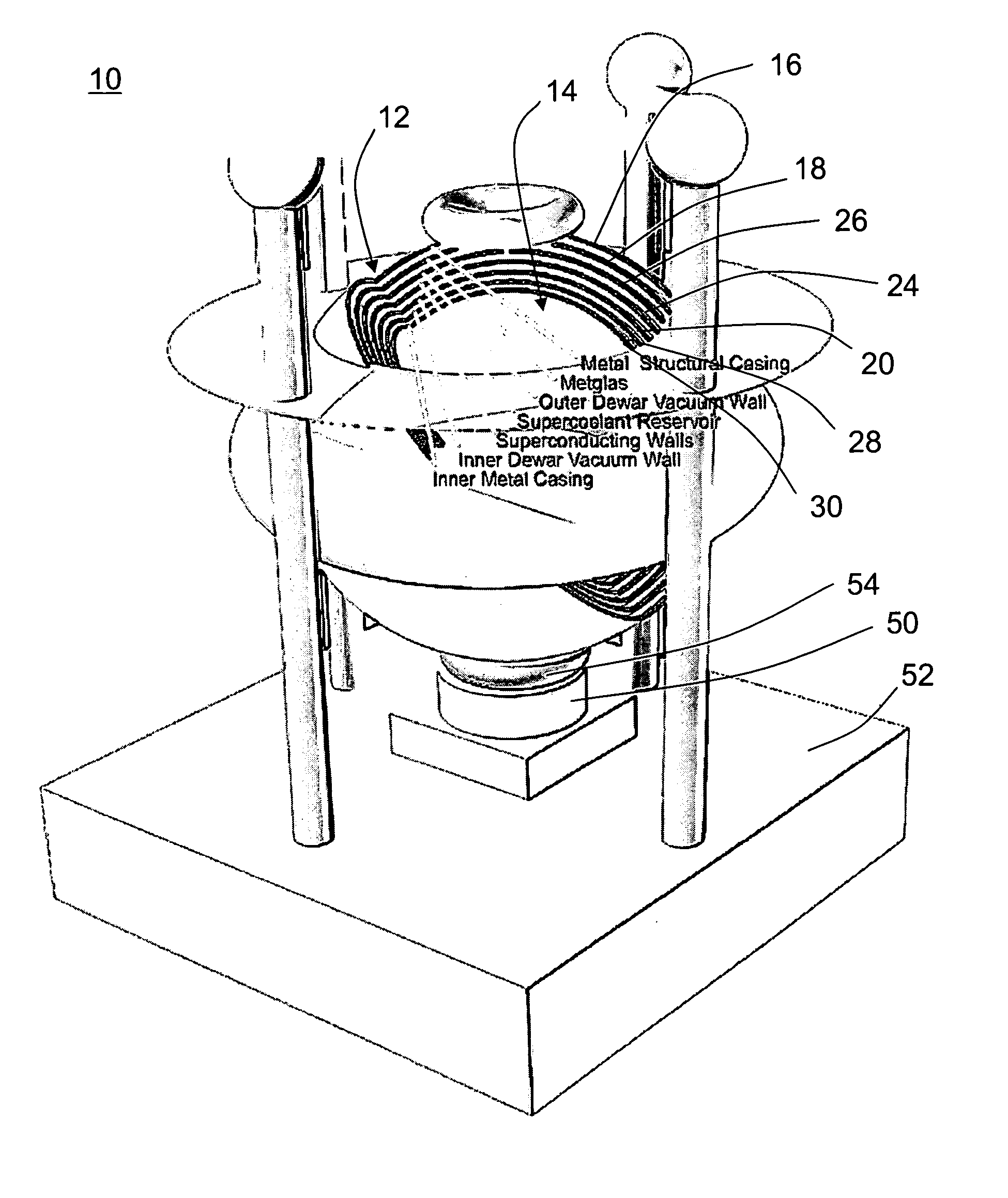
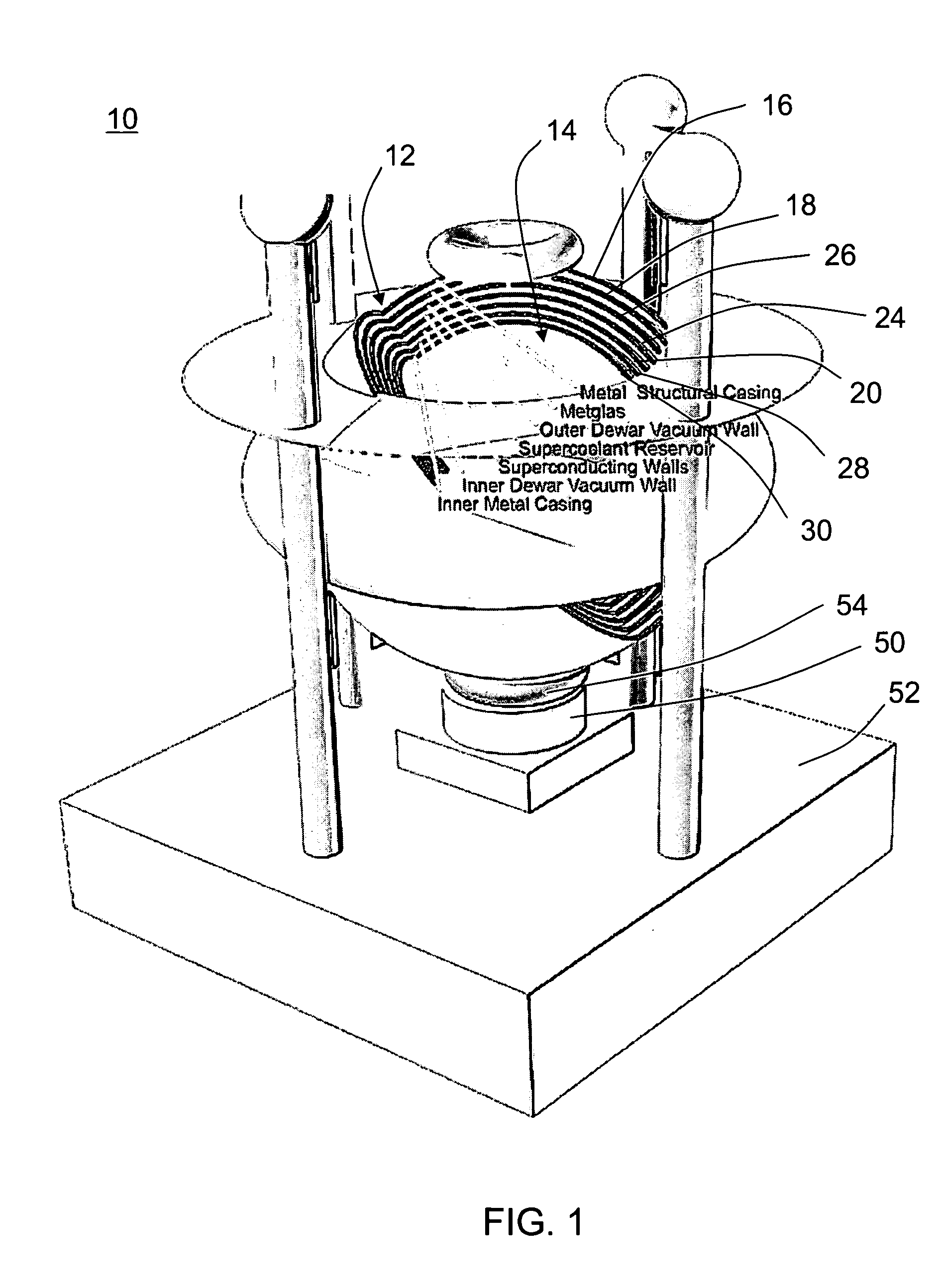
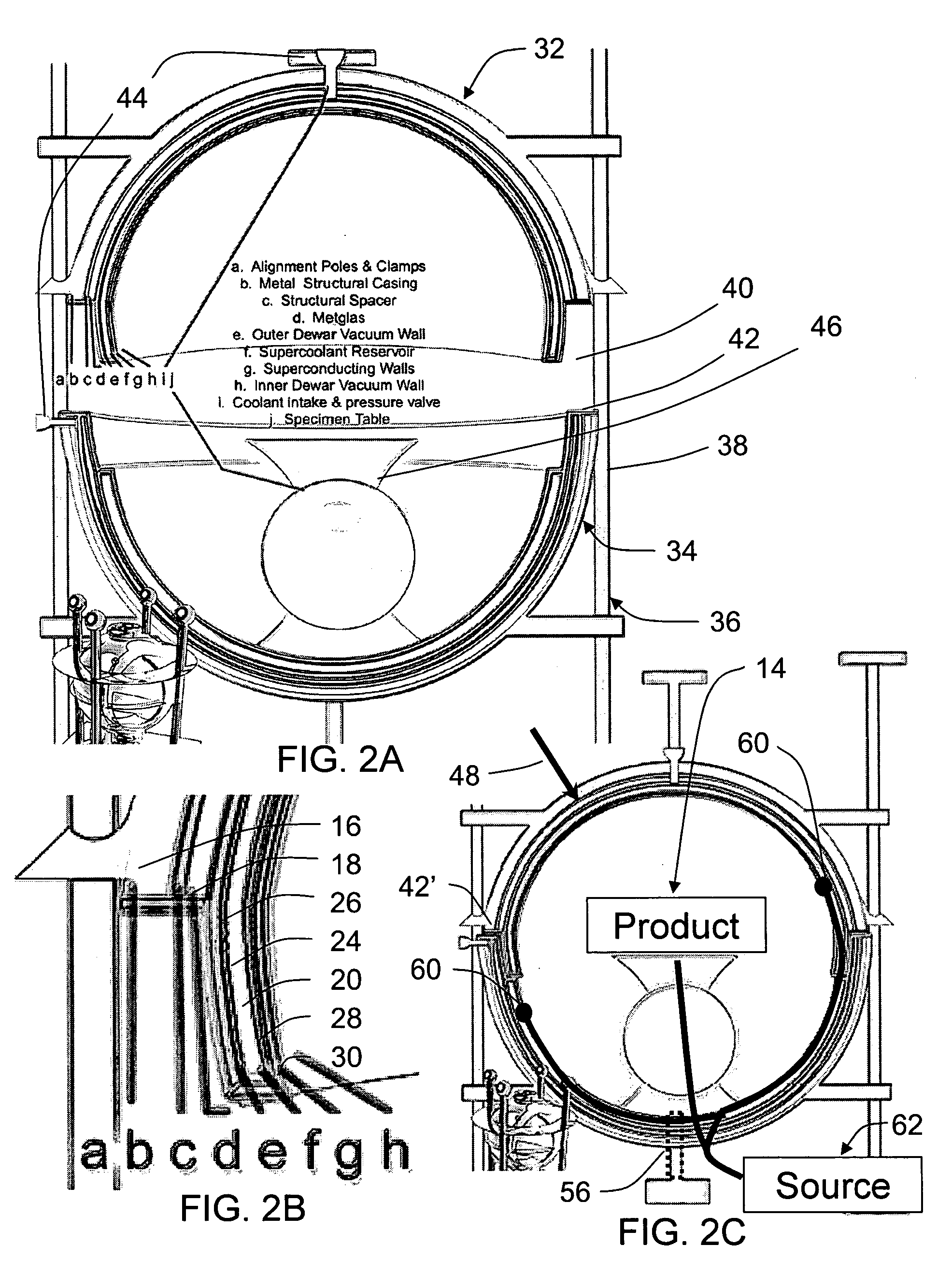
[0021] Referring to the accompanying drawings in which like reference numbers indicate like elements, FIG. 1 illustrates a cutaway view of the spheric alignment mechanism chamber 10 in an exemplary embodiment. The chamber 10 is formed in layers as a series of nested shells 12 which surround the work product 14 at the interior portion of the chamber 10. An outer structural casing 16 forms the exterior surface of the chamber 10. Within the structural casing 16, an electromagnetic shield 18 which surrounds a superconducting shell 20. The superconducting shell 20 is preferably immersed in a cryogenic coolant 22 contained in a reservoir 24. The reservoir 24 is preferably formed by a pair of Dewar flasks 26, 28 on opposite sides of the superconducting shell 20, i.e. the superconducting shell is sealed between the outer Dewar flask 26 and inner Dewar flask 28. The inner Dewar flask 28 is preferably protected by an inner casing 30 around the interior portion of the chamber 10.

[0022] As ill...


PUM


Abstract

A chamber for manipulating a work product is formed in layers as a series of nested shells. The shells have an outer structural casing and an electromagnetic shield that surrounds a superconducting shell. The superconducting shell is immersed in a cryogenic coolant contained in a reservoir. The work product is further manipulated using kinetic energy and electromagnetic energy.

Description

CROSS-REFERENCE TO RELATED APPLICATIONS [0001] This application claims the benefit of U.S. Provisional Application Nos. 60 / 563,427, 60 / 564,013 and 60 / 570,514, respectively filed on Apr. 19, 2004, Apr. 21, 2004 and May 12, 2004, and the disclosures of these provisional applications are incorporated herein by reference.BACKGROUND OF THE INVENTION [0002] 1. Field of the Invention [0003] The present invention relates to superconductive materials, and more particularly, to a superconducting shell with electromagnetic shielding surrounding a work product in an entropically isolated environment. [0004] 2. Related Art [0005] Generally, quantum physics predicts that all of space is filled with zero-point fluctuations, also called the zero-point field, creating a universal sea of zero-point energy. The density of this energy depends critically on where in frequency the zero-point fluctuations cease. Since space itself is thought to break up into a kind of quantum foam at a tiny distance scale...

Claims


Application Information

Patent Timeline
Patent Type & Authority Applications(United States)
IPC IPC(8): G21G1/00
CPCG21F1/125
Inventor KESSLER, STEPHEN BURNS
Owner KESSLER STEPHEN BURNS
Learn More