
Layered product, electromagnetic-shielding molded object, and processes for producing these

a technology of electromagnetic shielding and molded objects, applied in the field of layered products, can solve the problems of inconvenient thermosetting resin layered product, difficult reduction of production cost, etc., and achieve the effects of reducing weight, and reducing thickness and weigh

Active Publication Date: 2006-05-25
TORAY IND INC
View PDF5 Cites 145 Cited by
  • Summary
  • Abstract
  • Description
  • Claims
  • Application Information

AI Technical Summary

Benefits of technology

[0090] An example of the state of the test piece obtained by carrying out the third testing method is shown in FIG. 7. FIG. 7 shows a joint portion 61 where the surface of the layered product A1 was bonded to the end of the adhering member B1. Partially in the joint portion 61, a partial residue 62 of the surface layer portion of the layered product A1 is observed. It can be observed that plural filaments coming off from the groups of reinforcing fibers positioned in the surface layer of the layered product A1 exist in the residue 62. On the other hand, in the case where such a residue does not adhere to the adhering member B1 or in the case where filaments are not observed in the residue, the resin of the thermoplastic resin layer on the surface does not permeate into the clearances among the groups of reinforcing fibers in the layered product. Such a layered product does not have the working effect of the invention.
[0091] The structural feature of the layered product of the invention can be verified by at least one of the above-mentioned testing methods.
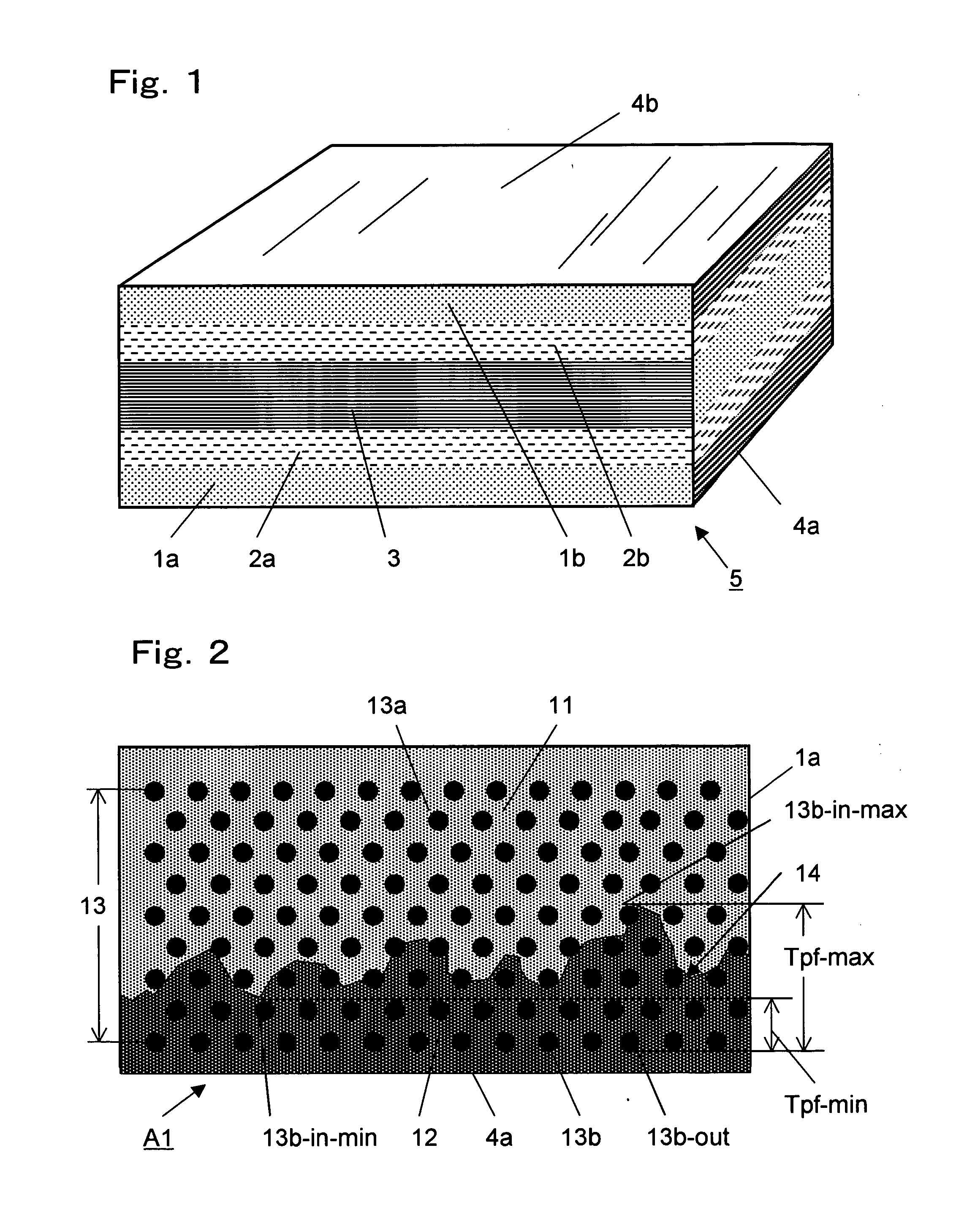
[0092] For the purpose of enhancing the bonding strength of the layered product A1 of the invention to another adhering member B1, it is preferred that the maximum thickness Tpf of the area where the continuous filaments 13b exist in the thermoplastic resin layer 12 is 10 μm or more. More preferred is 20 μm or more, and further more preferred is 40 μm or more. The maximum thickness Tpf-max is defined as the distance (Tpf-max) between the outermost (surface side) filament 13b-out kept in contact with the resin of the thermoplastic resin layer 12 in the thickness direction of the thermoplastic resin layer 12 and the innermost filament 13b-in-max kept in contact with the resin of the thermoplastic resin layer 12 in the region where the penetrating thickness of the resin of the thermoplastic resin layer 12 from the surface is largest. The maximum thickness Tpf-max can be measured on a photograph of SEM or TEM obtained by the first or second testing method. If the maximum thickness Tpf-max is 1,000 μm at the largest, the effect of the invention can be sufficiently achieved.
[0093] The minimum thickness Tpf-min is defined as the distance (Tpf-min) between the outermost (surface side) filament 13b-out kept in contact with the resin of the thermoplastic resin layer 12 in the thickness direction of the thermoplastic resin layer 12 and the innermost filament 13b-in-min kept in contact with the resin of the thermoplastic resin layer 12 in the region where the penetrating thickness of the resin of the thermoplastic resin layer 12 from the surface is smallest.
[0094] In the layered product A1, it is preferred that the interface 14 between the thermosetting resin layer 11 and the thermoplastic resin layer 12 exists among the groups of reinforcing fibers 13 consisting of numerous filaments 13a and 13b paralleled in one direction as shown in FIG. 2. In the case where the groups of reinforcing fibers 13 exist in plural layers in the thickness direction in the layered product A1, it is usually sufficient that the interface 14 exists in the groups of reinforcing fibers 13 of the outermost layer.
[0095] It is preferred that the resin forming the thermosetting resin layer 11 of the layered product A1 of the invention underwent the setting reaction, to ensure that the layered product A1 obtained has excellent mechanical properties. It is preferred that the glass transition temperature of the thermosetting resin is 60° C. or higher. More preferred is 80° C. or higher, and further more preferred is 100° C. or higher. The glass transition temperature is measured by a publicly known measuring method using a differential scanning calorimeter (DSC). For example, the thermosetting resin layer 11 of the layered product A1 is cut out without separating the groups of reinforcing fibers 13, to prepare a test piece, and from the endothermic peak of the test piece, the glass transition temperature is specified. As the setting reaction of the thermosetting resin progresses, the glass transition temperature shifts toward a higher temperature, and accordingly, the endothermic peak tends to be smaller.

Problems solved by technology

However, an FRP composed of a thermosetting resin is not suitable for producing a complicatedly shaped part or structural body by a single molding process.
A mechanical bonding method has such problems that the reduction of production cost is very difficult since a step for machining bonding portions beforehand is necessary and that application is limited in view of appearance.
A bonding method using an adhesive has such problems that the reduction of production cost is very difficult since a bonding step including the pre-arrangement of an adhesive and adhesive application work is necessary, and that no sufficiently satisfactory reliability can be obtained in the bonding strength.
However, there is a problem that the bonding strength at the joint between the thermosetting resin and the thermoplastic resin film in the surface member is not sufficient.
However, it is difficult to easily produce complicatedly shaped parts and products at high productivity from these metallic materials.
However, these housings cannot satisfy the demand for lighter weight, since the specific gravity of the metallic material is large, though they can satisfy the demand for smaller thickness and higher stiffness.
Considering the recycling of products, it is difficult to separate and sort the products obtained by integrating members formed of different materials into the respective members.
As a result, contaminants consisting of different materials are generated to pose such problems that it is difficult to reuse those members and that the cost of recycling increases.

Method used


Image

  • Layered product, electromagnetic-shielding molded object, and processes for producing these
  • Layered product, electromagnetic-shielding molded object, and processes for producing these
  • Layered product, electromagnetic-shielding molded object, and processes for producing these

Examples


first embodiment

of the Layered Product of the Invention:

[0067]FIG. 1 shows a layered product 5. The layered product 5 consists of five layers sequentially laminated from a bottom face 4a to a top face 4b. That is, the layered product 5 consists of a first layer 1a, a second layer 2a, a third layer 3, a fourth layer 2b and a fifth layer 1b.

[0068]FIG. 2 shows an expanded sectional view showing a part of the first layer 1a. FIG. 2 was prepared based on a photograph obtained by photographing a cross section of a part of the first layer 1a using a scanning electron microscope (SEM).

[0069] The first layer 1a is an example of the layered product A1 of the invention. The layered product A1 (first layer 1a) comprises a thermosetting resin layer 11, a thermoplastic resin layer 12 and groups of reinforcing fibers 13 comprising numerous continuous filaments 13a and 13b. The thermosetting resin layer 11 and the thermoplastic resin layer 12 are integrated while forming ruggedness at the interface 14 between th...

second embodiment

of the Layered Product of the Invention:

[0103]FIG. 9 shows an integrated molded object C2. In FIG. 9, the molded object C2 consists of a layered product A2 of the invention forming a top board 101 and a structural member B2 forming a frame 102. In the molded object shown in FIG. 9, the top board 101 (layered product A2) is integrated with the top faces of the rise wall portions of the frame 102 (structural member B2), and it is an example of the electromagnetic-shielding molded object C2 such as a personal computer housing.

[0104] In FIG. 9, the layered product A2 (top board 101) of the invention as a component of the electromagnetic-shielding molded object C2 consists of a thermosetting resin as the matrix resin and groups of conductive continuous reinforcing fibers arranged in the resin, and has a film made of a thermoplastic resin composition described later formed at least partially on the surface of the layered product A2 (top board 101) (since this surface is the bottom face o...

examples

[0202] The invention is described below more particularly based on examples and comparative examples. All the mixing rates (%) shown in the examples and comparative examples are values based on weight percent, unless otherwise stated.


PUM

PropertyMeasurementUnit
Temperatureaaaaaaaaaa

Abstract

A layered product which is a molded object comprising a thermoset resin layer, a thermoplastic resin layer, and reinforcing fibers comprising many continuous filaments, wherein the thremoset resin layer has been united with the thermoplastic resin layer at the interface between these layers, the resin of the thermoset resin layer and the resin of the thermoplastic resin layer each having an irregular surface shape at the interface, and a group of filaments among the reinforcing fibers are in contact with at least the resin of the thermoset resin layer and the other group of filaments among the reinforcing fibers are in contact with at least the resin of the thermoplastic resin layer, that side of the thermoplastic resin layer which is opposite to the interface being a surface of the molded object.

Description

TECHNICAL FIELD [0001] The present invention relates to a layered product composed of a fiber reinforced resin reinforced by groups of reinforcing fibers consisting of numerous continuous filaments, and also to a process for producing it. The invention also relates to a layered product capable of being strongly integrated with another structural member, especially a structural member composed of a thermoplastic resin. The invention also relates to a layered product capable of being integrated with another structural member to form a molded object that can be easily decomposed and sorted into respective parts for allowing the reuse of the parts when the molded object is scrapped as waste. [0002] The invention also relates to an electromagnetic-shielding molded object formed by integrating a layered product composed of a fiber reinforced resin reinforced by groups of reinforcing fibers consisting of numerous continuous filaments and another structural member. [0003] The integrated mol...

Claims


Application Information

Patent Timeline
IPC IPC(8): B32B27/00B32B27/04H05K9/00
CPCB32B5/10Y10T428/2826B60K15/03177B60K2015/03046H05K9/009B29C66/919B29C66/91921B29C66/91935B29C66/91943B29C66/1122B29C65/4815B29C65/5057B29C65/8215B29C66/0242B29C66/30322B29C66/43B29C66/7212B29C66/73752B29C66/73941B29C66/91445B29C66/91933B29C66/929B29C66/949B29C70/00B29C65/02B29C66/3034B29C66/72141B32B27/04Y10T428/24364B29C66/73115B29C66/73117Y10T428/2896B29K2307/04B29C66/8322B29C66/7392B29C66/7394B29C66/73161B29C66/71B29C65/08B29C65/16B29L2031/7172Y10T428/249924Y10T428/31786Y10T428/31938Y10T428/31551Y10T428/249945Y10T428/31855Y10T428/249942Y10T428/31739Y10T428/31511Y10T428/31725Y10T428/24995Y10T428/31935Y10T428/31507Y10T428/249952Y10T428/31504B29C66/742B29C66/7422B29C66/74283B29C70/0035B29K2077/00B29K2069/00B29K2067/00B29K2081/04B29K2063/00B29K2075/00B29K2033/08B29K2025/04B29K2023/083B29K2023/00B32B2262/106B32B2305/08B32B2260/046B32B2260/021B32B5/022B32B5/26B32B2605/00B32B5/24B32B2457/00B32B2535/00
Inventor HONMA, MASATOISHIBASHI, SOUICHITAKEBE, YOSHIKIOBARA, HARUONISHIZAWA, TAKESHISHIHO, KOSUKEETO, SEICHIROHASEGAWA, TAKASHITANISUGI, HIDEAKI
Owner TORAY IND INC
Learn More