Means to regulate water velocity through a hydro electric turbine

a technology of hydroelectric turbines and water pipes, applied in the direction of liquid fuel engines, renewable energy generation, greenhouse gas reduction, etc., can solve the problem of relativly slow water velocity, usually between 1 and 5 knots, and achieve the effect of slow water velocity and increased water velocity

Inactive Publication Date: 2005-12-01
OPENHYDRO GRP LTD
View PDF6 Cites 10 Cited by
  • Summary
  • Abstract
  • Description
  • Claims
  • Application Information

AI Technical Summary

Benefits of technology

[0012] One of the problems inherent in a low head (run of the river, tidal, etc.) turbine for producing electricity is the relatively slow water ve...

Problems solved by technology

One of the problems inherent in a low head (run of the river, tidal, etc.) turbine f...

Method used


Image

  • Means to regulate water velocity through a hydro electric turbine
  • Means to regulate water velocity through a hydro electric turbine
  • Means to regulate water velocity through a hydro electric turbine

Examples


Embodiment Construction

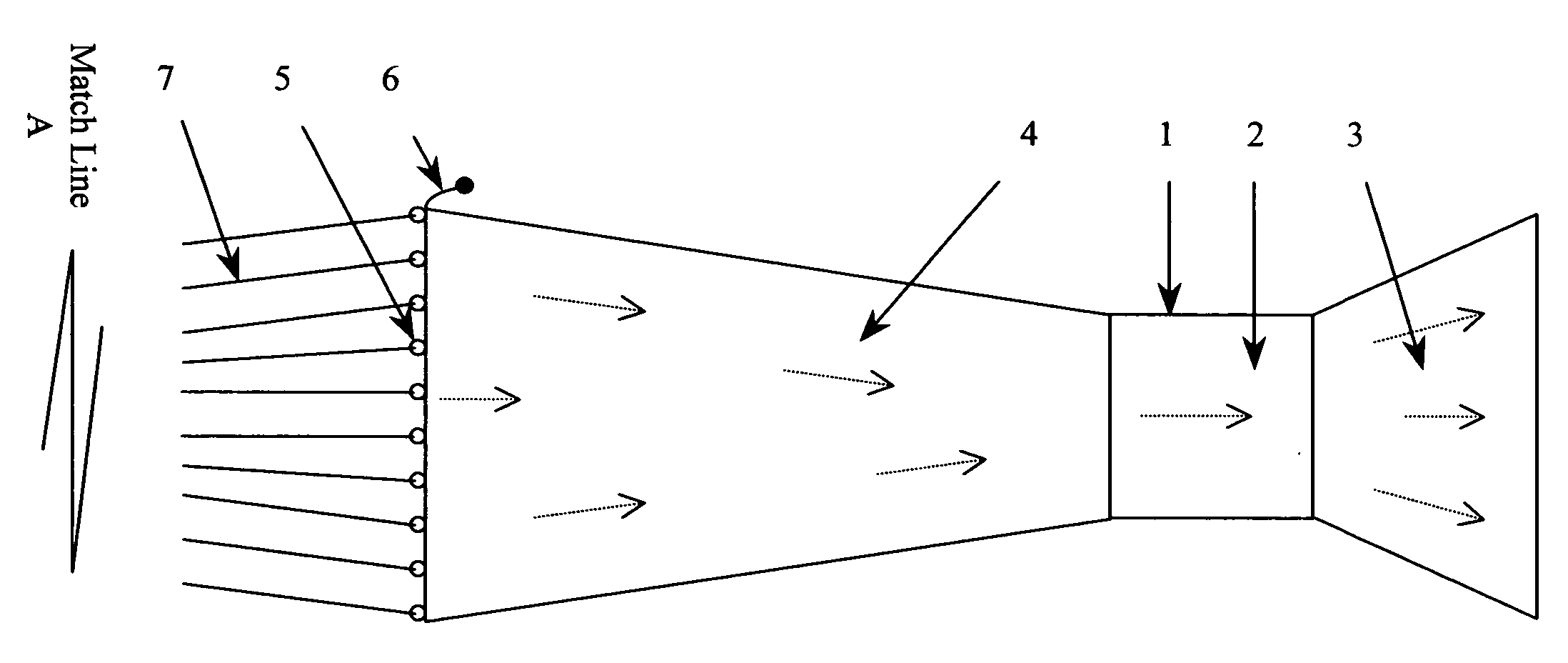
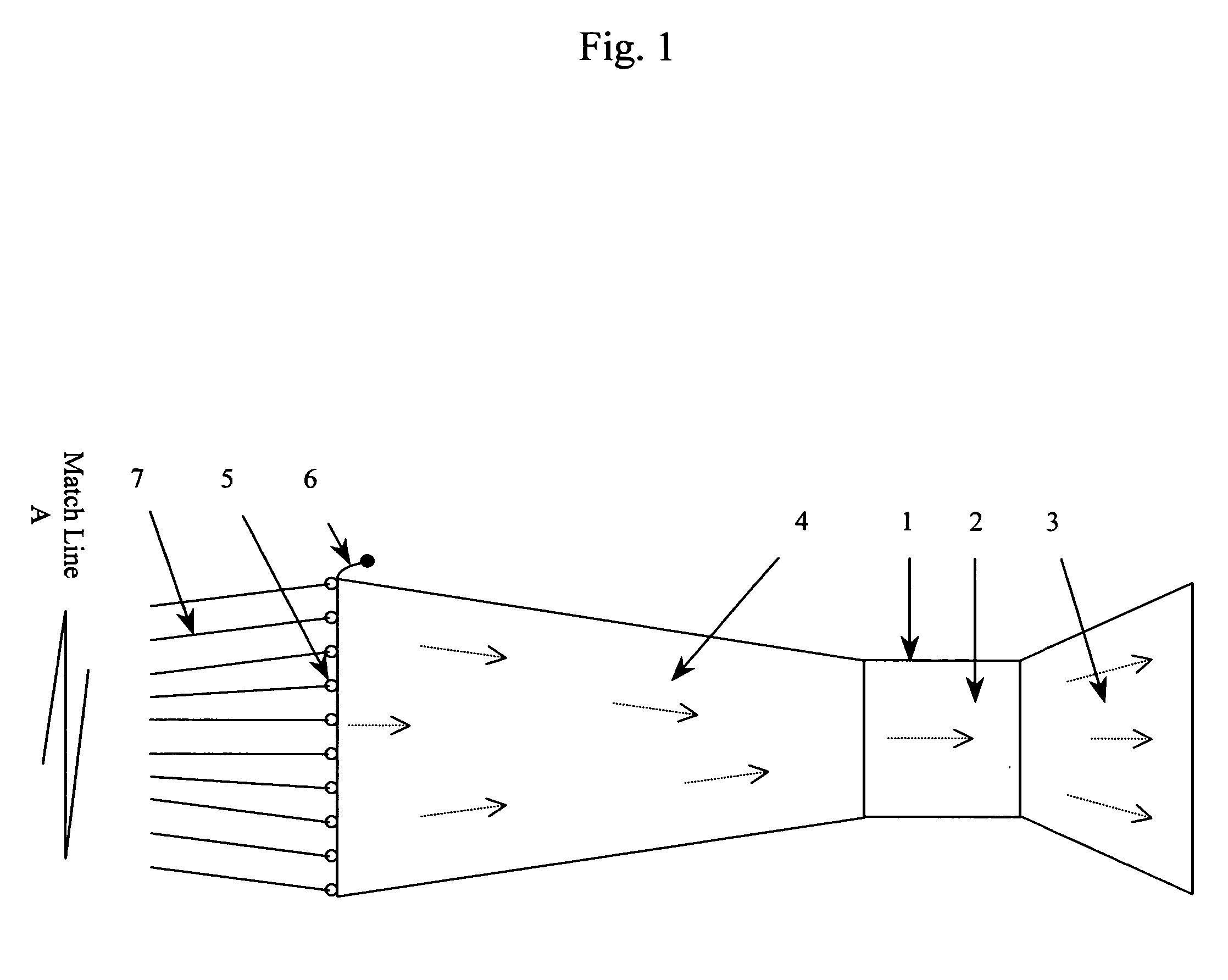
[0017] As the water flows through front shroud (4), it's velocity and pressure increases. When the flow enters turbine housing (1), it has reached maximum velocity and pressure. It is in the area (2) that the work is being done of rotating the turbine blades. As the water passes through the rear shroud (3), its velocity and pressure is decreased continually until it merges again with the outside flow.

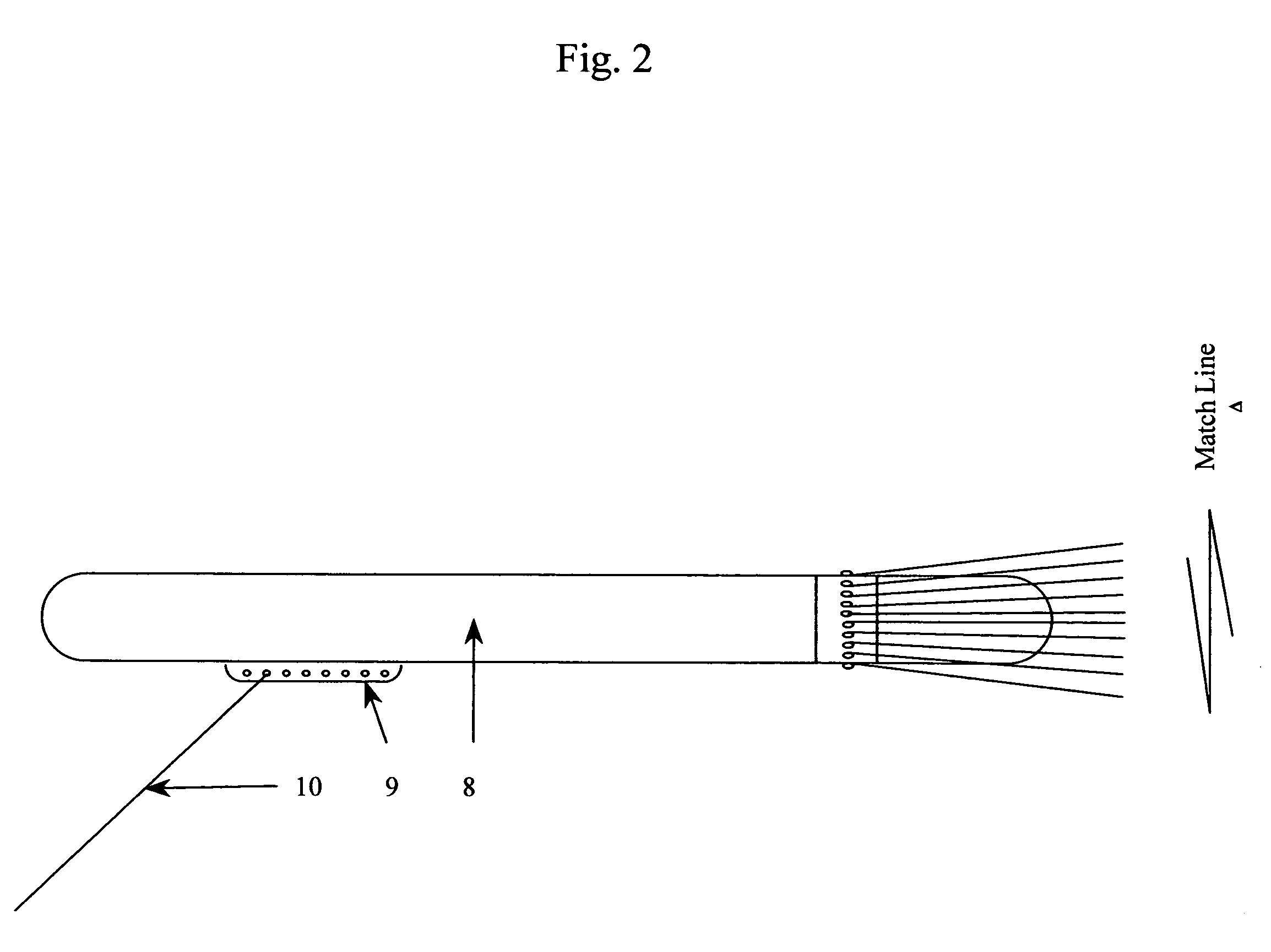
[0018] The draw line (6) which passes through all the purse rings (5) and is attached at one end to the front of the shroud (4) has the ability when pulled, to purse (draw together) the purse rings (5) and stop the water flow through the turbine. When the draw line (6) is released, the shroud (4) will again open, allowing water to pass through the turbine. The cable (7) attaches the front shroud (4) to the flotation chamber (8).

[0019] The scope angle adjustment (9) is where the anchor line (10) is attached to the flotation chamber (8). By adjusting the attachment point of the anchor l...


PUM


Abstract

The embodiment is a venturi front shroud that can be pursed or released to decrease or increase water velocity through the housing of a turbine.

Description

CROSS-REFERENCE TO RELATED APPLICATIONS [0001]“Not Applicable”STATEMENT REGARDING FEDERALLY SPONSORED RESEARCH OR DEVELOPMENT [0002]“Not Applicable”REFERENCE TO A MICROFICHE APPENDIX [0003]“Not Applicable”BACKGROUND OF THE INVENTION [0004] This patent application follows the provisional application No. 60 / 472,092 with the filing date May 21, 2003, titled, “Means to increase water velocity through a hydro electric turbine”. [0005] The method of using a venturi to increase the velocity of a water flow is old. The embodiment has the following aspects which the inventor believes are new. [0006] 1) The front shroud is flexible (collapsible) on demand. [0007] 2) The front shroud can be pursed (drawn) together to stop water from flowing through it and the turbine. [0008] 3) The purse line can be released to allow water to flow through the front shroud and turbine. [0009] 4) A combination of a flexible front and a rigid rear shroud used together as one unit. [0010] 5) The method of pursing ...

Claims


Application Information

Patent Timeline
IPC IPC(8): F01D1/00F03B3/04
CPCF03B3/18F03B3/183F03B15/14F03B17/061F05B2240/12F05B2240/133Y10S415/906F05B2250/232F05B2250/5011Y02E10/223Y02E10/226Y02E10/28F05B2240/97Y02E10/20Y02E10/30
Inventor WILLIAMS, HERBERT L.
Owner OPENHYDRO GRP LTD
Why Eureka
Try Eureka