Process for printing and molding a flocked article

a technology of flocked articles and moldings, applied in the direction of weaving, dyeing process, transportation and packaging, etc., can solve the problems of impracticality and cumbersome, and achieve the effect of reducing the cost of production, and improving the quality of production

Inactive Publication Date: 2005-12-01
HIGH VOLTAGE GRAPHICS
View PDF99 Cites 45 Cited by
  • Summary
  • Abstract
  • Description
  • Claims
  • Application Information

AI Technical Summary

Benefits of technology

[0007] The flock of the present invention comprises a printable flocking material. Typically, the flocking material is a white polyester or other synthetic fiber. A suitable dye or pigment is applied to the flock to cause dying or coloration of the flock after application to the underlying (or overlying) layer (depending on the order in which the various layers are deposited). The dyes or pigments include sublimation dyes (as noted above), acid dye inks, and pigment dyes. Sublimination is a preferred technique to provide desired color patterns to the design due to the superior feel of the design. The colored fibers in the design have a softer feel than fibers colored using other techniques or of other compositions. A softer feel is more attractive to consumers i

Problems solved by technology

Unlike sublimation dyes, non-sublimation dyes, such as acid dye inks, generally must be c

Method used


Image

  • Process for printing and molding a flocked article
  • Process for printing and molding a flocked article
  • Process for printing and molding a flocked article

Examples


first embodiment

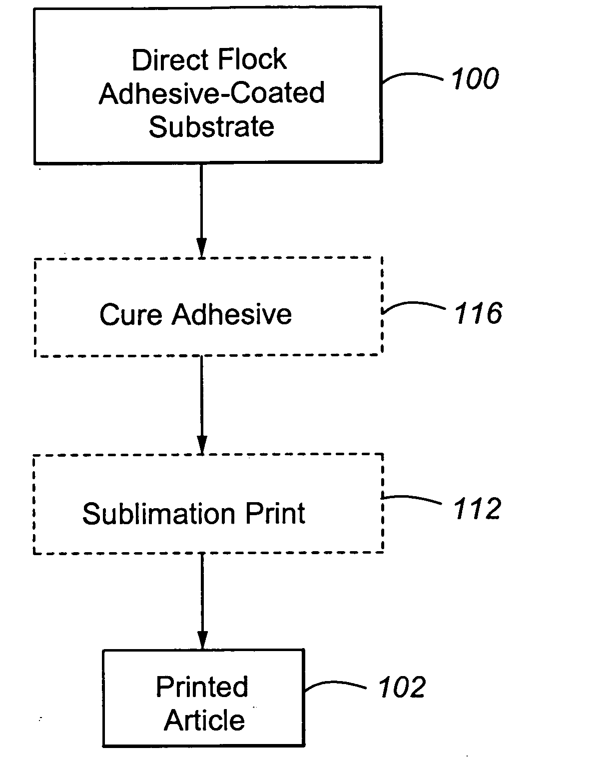
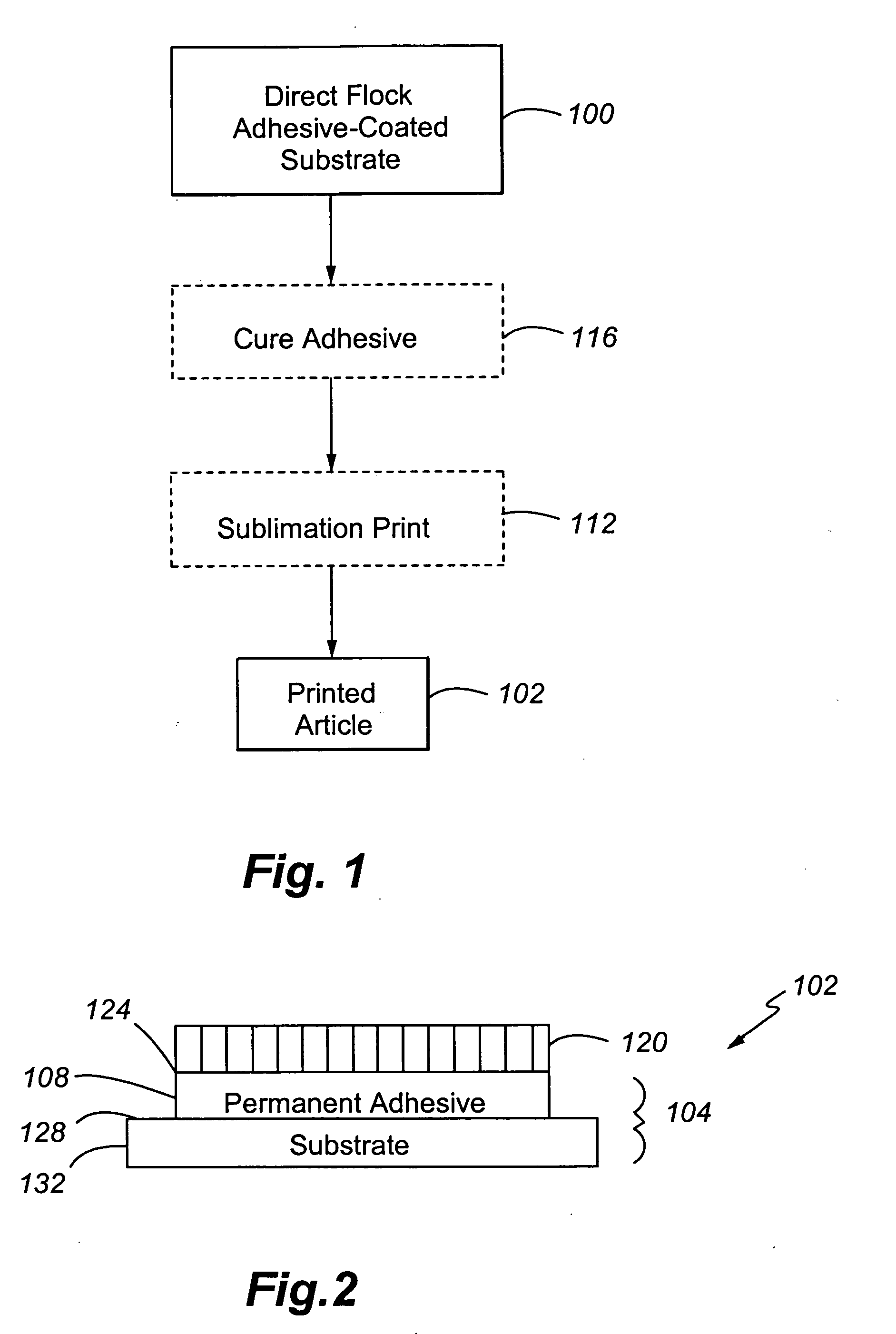
[0049] Referring to FIGS. 1 and 2, the process and article of the present invention will now be described. This process is further discussed in U.S. Provisional Application Ser. Nos. 60 / 366,580 filed Mar. 21, 2002; 60 / 393,362, filed Jul. 3, 2002; and 60 / 416,098 filed Oct. 4, 2002, each of which is incorporated herein by reference.

[0050] In the first step 100, an adhesive-coated substrate 104 is direct flocked by known techniques using the flock of the present invention. The flock is typically white in color and can be flocked by any suitable technique, with electrostatic flocking being preferred. The adhesive may be applied discontinuously to the substrate in a desired (direct) image.

[0051] The adhesive used in adhesive layer 108 may be any suitable permanent adhesive (as opposed to a release adhesive) that is thermally compatible with the sublimation printing temperature used in step 112. “Thermal compatibility” depends on the process configuration. When the adhesive is cured (e.g...

second embodiment

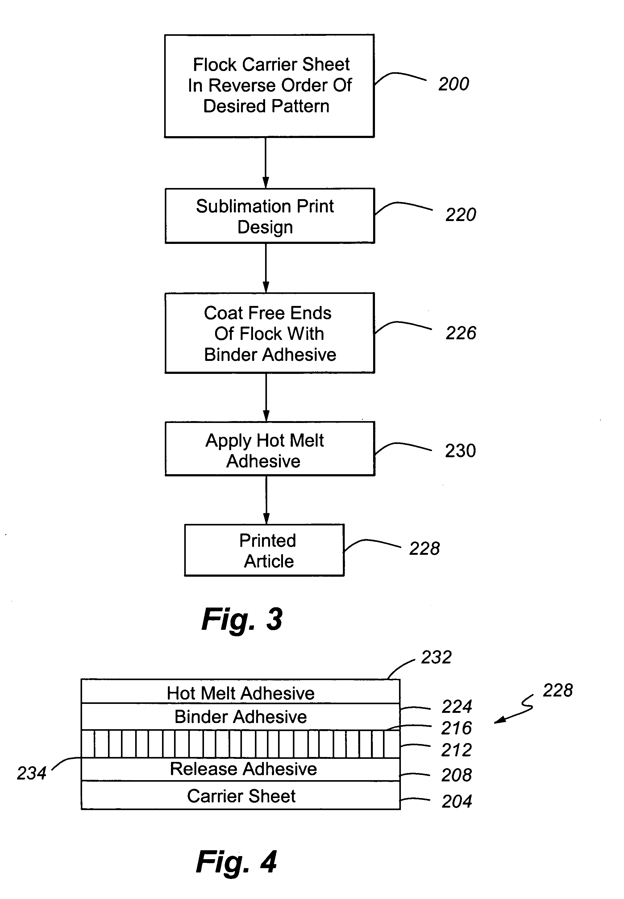
[0060] Referring to FIGS. 3 and 4, the process and article of the present invention will now be described. This process is further discussed in U.S. Pat. Nos. 4,810,549; 5,207,851; 5,597,637; 5,858,156; 6,010,764; 6,083,332; and 6,110,560, each of which is incorporated herein by this reference.

[0061] In step 200, the carrier sheet 204 containing a temporary release adhesive 208 (such as wax) in the reverse of the desired pattern or image is flocked by suitable techniques, preferably electrostatically, with the flock of the present invention.

[0062] The carrier sheet 204 can be any suitable transfer carrier, such as dimensionally stable paper, processed paper, plastic film, resin sheets, and metal foils. Depending on the desired effect and the sheet materials employed, the carrier can be transparent, translucent, or opaque, but is typically transparent. Typically (but not always), the primary carrier is a discontinuous sheet as opposed to a continuous sheet on a running web line.

[00...

third embodiment

[0068] Referring to FIGS. 5 and 6, the process and article of the present invention will now be described. This process is further discussed in U.S. patent Ser. Nos. 09 / 548,839; 09 / 35,721; and 09 / 621,830, each of which is incorporated herein by this reference. PCT-containing and bicomponent fibers are ideal fibers to withstand the temperature and pressure used in the lamination process in this configuration.

[0069] In step 500, the carrier sheet 504 containing a temporary release adhesive 508 (such as wax) in the reverse of the desired pattern or image is flocked by suitable techniques, preferably electrostatically, with the flock of the present invention.

[0070] The exposed ends 512 of the flocked surface 516 are then sublimation printed in step 520 by the techniques discussed previously. As noted, vacuuming of the flock can be conducted before or after sublimation printing.

[0071] The exposed, printed ends 512 of the flocked surface are next contacted with a first permanent adhesiv...


PUM

PropertyMeasurementUnit
Temperatureaaaaaaaaaa
Fractionaaaaaaaaaa
Fractionaaaaaaaaaa

Abstract

The processes and articles of the present invention use thermally stable and loft retentive polymers in sublimation printed flock fibers, which are particularly attractive for forming molded articles. A preferred fiber is a multi-component (composite) fiber, such as a bicomponent fiber.

Description

CROSS REFERENCE TO RELATED APPLICATIONS [0001] The present application claims the benefits under 35 U.S.C. § 119 of U.S. Provisional Patent Application Ser. No. 60 / 537,110, filed Jan. 16, 2004, of the same title and to the same inventor, which is incorporated herein by this reference.FIELD OF THE INVENTION [0002] The present invention is related generally to printing of flocked articles and specifically to sublimation printing of flocked articles. BACKGROUND OF THE INVENTION [0003] Flock is used in the manufacture of numerous types of articles, such as textiles. Such articles are typically manufactured by electrostatically depositing the flock onto the desired surface. In one process, the desired surface is a release-adhesive coated sacrificial carrier sheet. The free ends of the flock are contacted with an adhesive. This structure, also known as a transfer, is thermally applied to the substrate. In another process, the desired surface is a permanent adhesive or the substrate itself...

Claims


Application Information

Patent Timeline
IPC IPC(8): B32B3/02B32B7/12
CPCB29C45/14811Y10T428/2938B29C2791/001B29C2791/006B29K2105/0818B29K2713/00B29K2715/006B29K2995/002B32B7/12B41M5/025B41M5/0256B41M5/035B41M7/009B41M2205/02D01F8/04D06P5/004D06P5/2077D06P5/30D06Q1/10D06Q1/14Y10T428/2933B29C51/10Y10T428/23943Y10T428/23986Y10T428/23993Y10T428/23914B32B38/145B32B37/12
Inventor ABRAMS, LOUIS BROWN
Owner HIGH VOLTAGE GRAPHICS
Why Eureka
Try Eureka