Modular floor terminal with damper

a module and floor terminal technology, applied in the field of module floor terminals, can solve the problems of unpredictable and uncontrollable performance, difficult to predict the effect of air current in the plenum, and difficult to plug and play installation, and achieve the effect of convenient and easy plug and play installation

Inactive Publication Date: 2005-12-01
E H PRICE
View PDF10 Cites 17 Cited by
  • Summary
  • Abstract
  • Description
  • Claims
  • Application Information

AI Technical Summary

Benefits of technology

[0005] The module floor terminal of the present invention includes a round floor boot terminal and a linear floor grille terminal. The round floor boot terminal consists of a square housing with a downwardly facing air inlet at the bottom and an upwardly facing air outlet at the top. The linear floor grille terminal consists of a rectangular housing with a downwardly facing air inlet at the bottom and an upwardly facing air outlet at the top. Both modular floor terminals have a rotating damper within the housing between the air inlet and the air outlet that is controlled by a floating point actuator that opens and closes the damper to vary the volume of air delivered through the air outlet to a diffuser grille and thereby to the occupied space above the floor.
[0008] The actuator control signal is supplied through a signal converter which allows for convenient and easy plug and play installation. A modular control cable can be plugged into the control interface at the actuator. The interface also includes an output for the signal to be carried to the next terminal if installed in a daisy-chain manner.
[0009] A perforated plate located in the air outlet of the terminal serves as an equalization baffle, ensuring consistent flow from the air outlet to the diffuser grille. This plate also serves to catch debris that may fall into the terminal from the occupied space through the diffuser grille.
[0010] Therefore, it is an object of the present invention to provide a modular floor terminal with a downwardly facing air inlet and a rotating damper that will provide consistent control of the air flow from the underfloor plenum, through the diffuser grille, to the occupied space above the floor.

Problems solved by technology

Any air movement in the plenum directed toward a terminal's air inlet, such as the side terminal air inlet of the prior art, could cause an unexpected pressure rise within the housing of the terminal.
This rise in pressure could lead to unpredictable and uncontrollable performance due to uneven loading of the terminals.
If the terminal's air inlet is not in line with the direction of airflow flow, the effects of air currents in the plenum are even harder to predict and will vary with the terminal's distance from the plenum inlets.

Method used


Image

  • Modular floor terminal with damper
  • Modular floor terminal with damper
  • Modular floor terminal with damper

Examples


Embodiment Construction

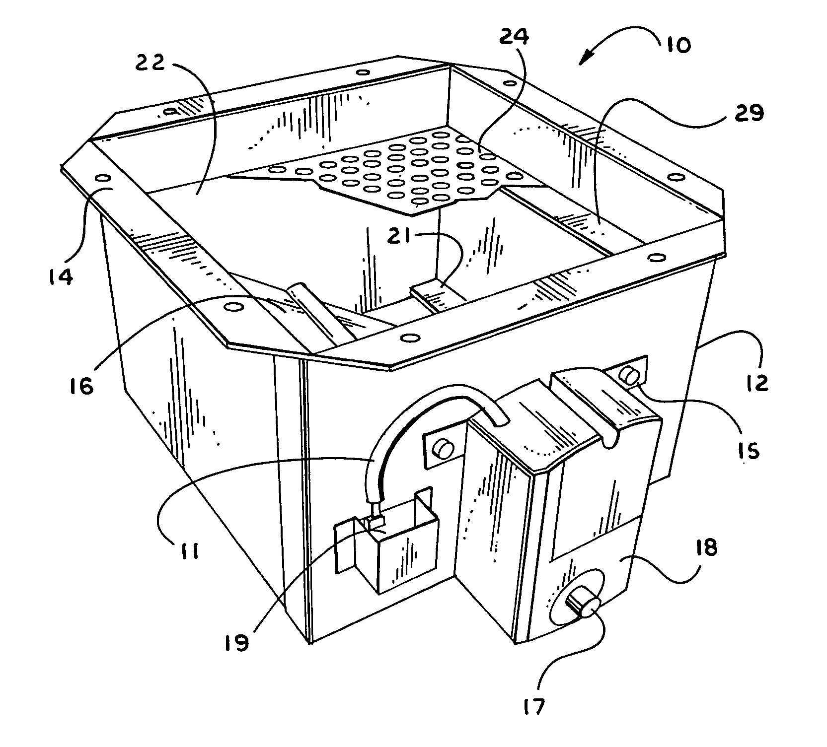
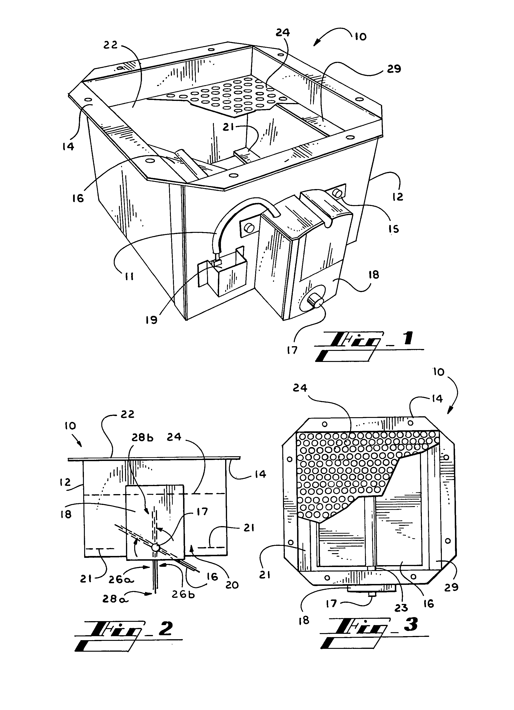
[0019] With reference to FIGS. 1-3, a round floor boot terminal 10 in accordance with the present invention is illustrated. The round floor boot terminal 10 consists of a square housing 12, an air inlet 20, an air outlet 22, a damper 16, and a floating point damper actuator 18. The square housing 12 consists of four sheet-metal sides. Extending mounting flanges 14 are located at the top of the housing 12 adjacent the air outlet 22. The air inlet 20 is downwardly facing at the bottom of the housing 12. A set of baffles 21 surround the air inlet 20 to restrict the size of the air inlet 20 to accommodate the size of the damper 16 (FIG. 2).

[0020] The rotating damper 16 is connected to a shaft 17 extending horizontally between two opposite sides of the housing 12. The floating point actuator 18 is mounted onto the housing 12 with a mounting plate 15 and connected to the shaft 17. The floating point actuator 18 rotates the shaft 17 through about a 90 degree range of motion to open and cl...


PUM


Abstract

A modular floor terminal mounted in the floor of an occupied space for delivering air from an underfloor air plenum to the occupied space. The modular floor terminal includes a square or rectangular housing with an air inlet at the bottom and an air outlet at the top. A rotating damper is positioned in the housing between the air inlet and the air outlet. The position of the damper is controlled by an actuator which is in turn controlled by a thermostat / controller in the occupied space above the floor.

Description

RELATED APPLICATION [0001] This application claims the benefit of priority of U.S. provisional application Ser. No. 60 / 575,108, filed May 27, 2004, which is relied on and incorporated herein by reference.FIELD OF THE INVENTION [0002] This invention relates to a modular floor terminal with a downwardly facing air inlet and a rotating damper. The modular floor terminal is used in connection with an underfloor plenum air conditioning system. BACKGROUND OF THE INVENTION [0003] In an underfloor plenum air conditioning system, cool air is supplied to the plenum below the floor of an occupied space to be cooled. In order to cool the occupied space above the floor, terminals are mounted in the floor at predetermined locations to allow the cool air in the plenum to flow into the occupied space above the floor. The terminals are located and oriented to accommodate the configuration of the occupied space to be cooled. [0004] Prior art configurations for modular floor terminals include simple b...

Claims


Application Information

Patent Timeline
Patent Type & Authority Applications(United States)
IPC IPC(8): F24F11/76F24F13/06F24F13/08F24F13/14
CPCF24F11/053F24F13/06F24F2221/40F24F13/14F24F13/08F24F11/76
Inventor RIMMER, JULIANNICHOLSON, MIKEDYCK, ALFREDMCCORRISTER, ANDREW
Owner E H PRICE
Why Eureka
Try Eureka