Wireless access system and method

Inactive Publication Date: 2005-12-01
PANASONIC CORP +1
View PDF11 Cites 124 Cited by
  • Summary
  • Abstract
  • Description
  • Claims
  • Application Information

AI Technical Summary

Benefits of technology

[0021] As described above, according to the present invention, it is possible to provide wireless LAN services over a wide area with one access point, and also possible to prevent degradation of transmission performance due to the hidden terminal problem. In addition, the slave station whose transmitted upstream signal h

Problems solved by technology

As is widely known, the area within which one access point can establish communication is limited by transmission power, etc.
The technique shown in FIG. 16 additionally installs an access point 513d so as to add an area d. This technique, however, involves increasing the number of expensive access points that require complex functions, such as radio-frequency conversion and channel conversion, resulting in a significant increase in system cost.
Moreover, if the user inst

Method used


Image

  • Wireless access system and method
  • Wireless access system and method
  • Wireless access system and method

Examples


first embodiment

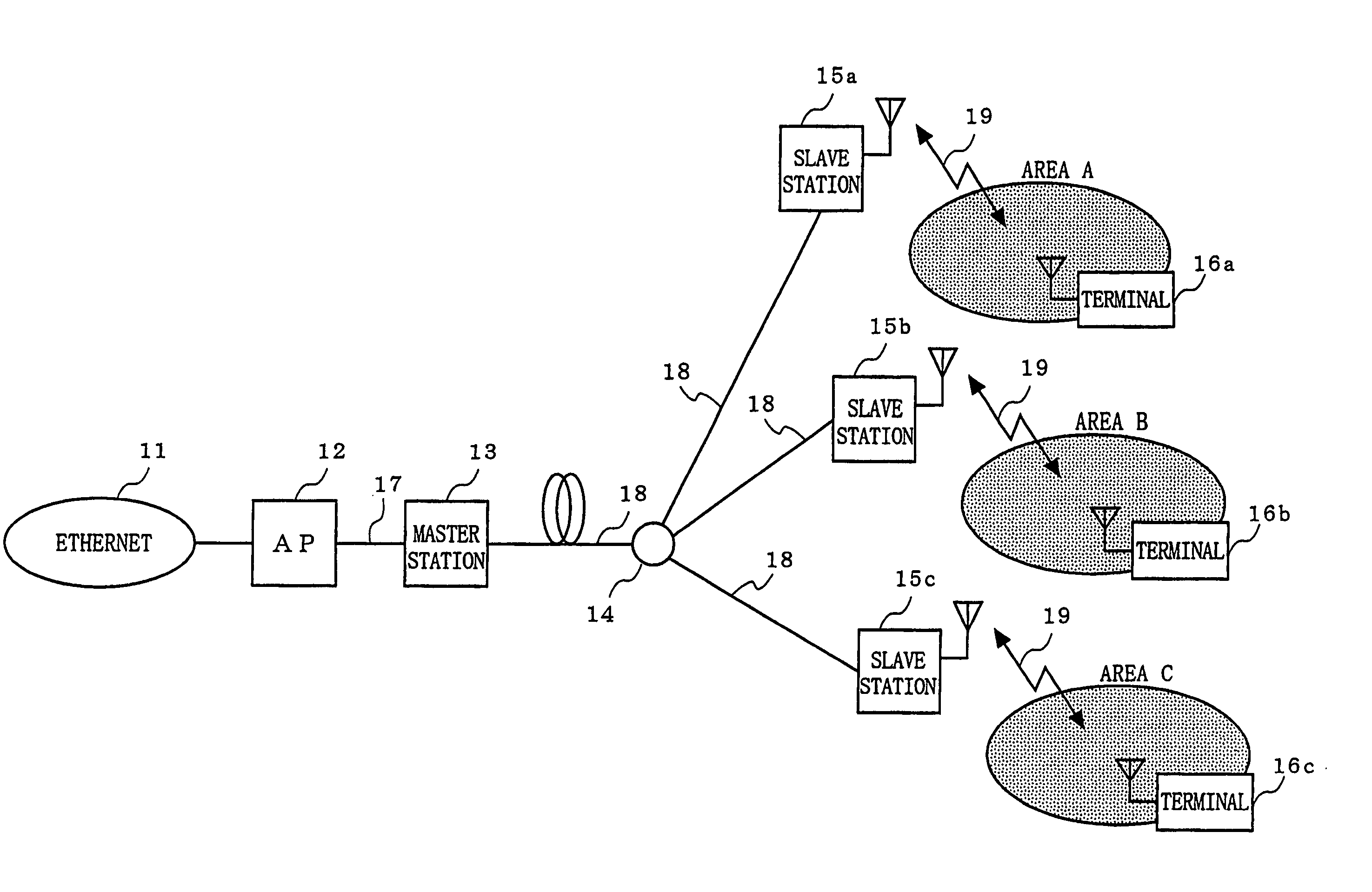
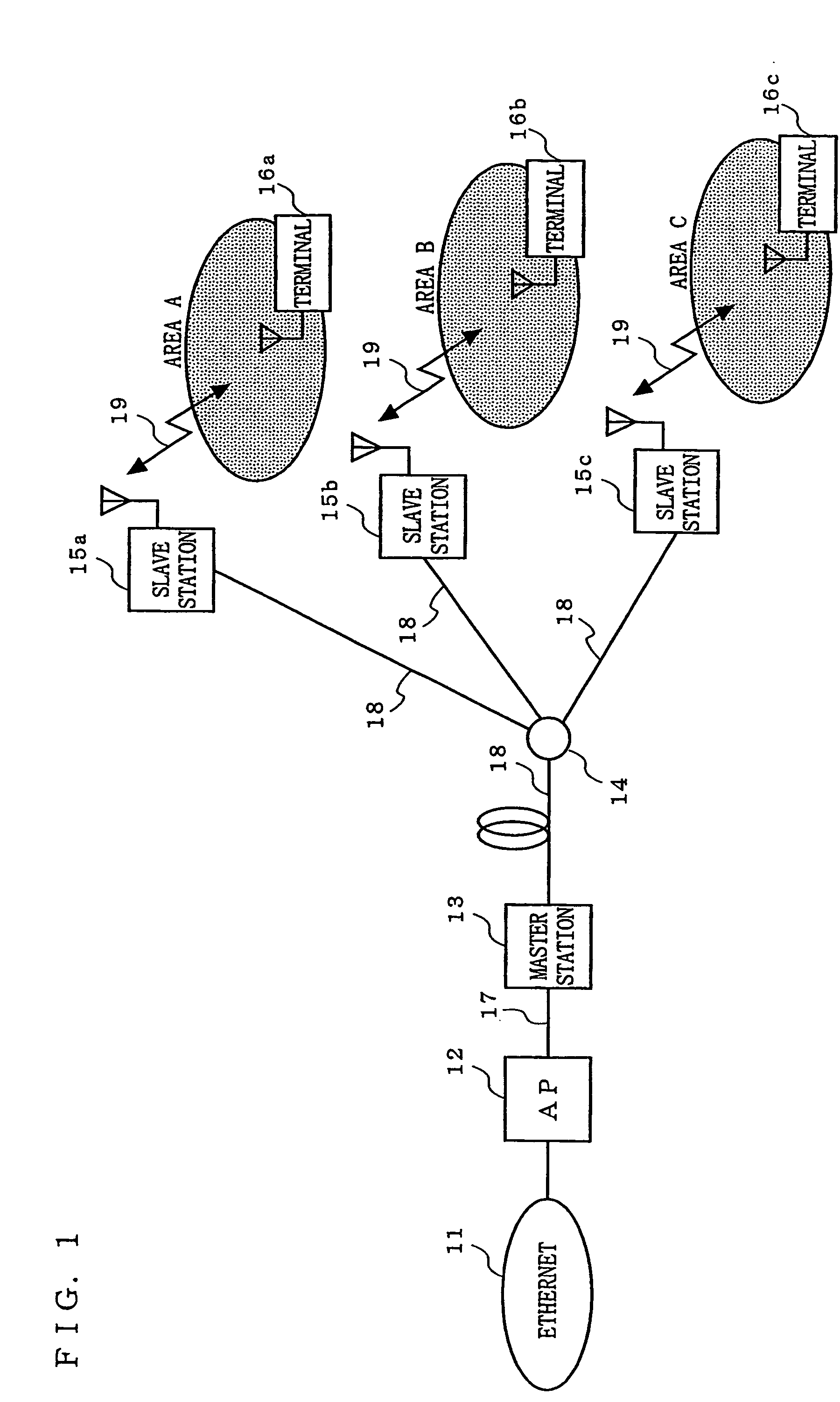
[0035]FIG. 1 is a block diagram illustrating a configuration of a wireless access system according to a first embodiment of the present invention. The wireless access system according to the first embodiment includes: an access point (AP) 12 connected to Ethernet network 11; a master station 13; an optical multiplexing / demultiplexing section 14 which serves as an access control section; slave stations 15a to 15c; and terminals 16a to 16c. The access point 12 and the master station 13 are connected to each other by an electrical cable transmission line 17. The master station 13 and the optical multiplexing / demultiplexing section 14, and the optical multiplexing / demultiplexing section 14 and the slave stations 15a to 15c are connected by optical fiber transmission lines 18. The slave stations 15a to 15c and the terminals 16a to 16c are connected by wireless transmission lines 19, respectively.

[0036] First, each component of the wireless access system according to the first embodiment...

second embodiment

[0049] The foregoing first embodiment describes a wireless access system with which the hidden terminal problem is solved by transmitting and receiving RTS and CTS packets before the actual data transmission takes place. On the other hand, a second embodiment will describe a wireless access system with which the hidden terminal problem is solved while performing the actual data transmission, without the need to perform transmission and reception of the packets.

[0050] The configuration of the wireless access system according to the second embodiment of the present invention is the same as that shown in the block diagram of FIG. 1, except that the transmission and reception of RTS and CTS packets are not performed between the master station 13 and the slave stations 15a to 15c, and that a special optical multiplexing / demultiplexing section 24 is used in place of the optical multiplexing / demultiplexing section 14. The wireless access system according to the second embodiment will be d...

third embodiment

[0057] The foregoing second embodiment describes a wireless access system that uses a special optical multiplexing / demultiplexing section 24 to solve the hidden terminal problem while performing the actual data transmission, without the need to perform transmission and reception of RTS and CTS packets. On the other hand, a third embodiment describes a wireless access system which, although using a typical optical multiplexing / demultiplexing section 14, does not need to perform transmission and reception of the packets.

[0058] The configuration of the wireless access system according to the third embodiment of the present invention is the same as that shown in the block diagram of FIG. 1, except that a master station 33 is used in place of the master station 13 and slave stations 35a to 35c are used in place of the slave stations 15a to 15c. The wireless access system according to the third embodiment will be described below with particular emphasis on the master station 33 and the s...


PUM


Abstract

A wireless access system and method are provided by which the wireless communications area covered by a single access point is increased while maintaining the maintainability of the access point, minimizing an increase in system cost, and avoiding the hidden terminal problem. An access point (12) and terminals (16a to 16c) are connected via a master station (13), an optical multiplexing/demultiplexing section (14), and slave stations (15a to 15c). A downstream signal to the terminals (16a to 16c) from the access point (12) is transmitted such that the master station (13) outputs the downstream signal to each of the slave stations (15a to 15c) in a distributed manner through the optical multiplexing/demultiplexing section (14). An upstream signal to the access point (12) from any one of the terminals (for example, 16a) is transmitted to the master station (13) through a slave station (for example, 15a) and the optical multiplexing/demultiplexing section (14), and also sent to all other slave stations (for example, 15b and 15c) through the master station (13) or the optical multiplexing/demultiplexing section (14).

Description

TECHNICAL FIELD [0001] The present invention relates to a wireless access system and method. More particularly, the invention relates to a wireless access system in which an optical transmission system is incorporated in a wireless LAN (Local Area Network) system using Carrier Sense Multiple Access (CSMA) for Media Access Control (MAC), and to a wireless access method performed by such a wireless access system. BACKGROUND ART [0002] An exemplary configuration of a conventional wireless LAN system is illustrated in FIG. 15. Such a conventional configuration example is disclosed in “Wireless LAN Technology Guide (Musen LAN gijutsu kouza)” by Matsushita et al., page 90, Soft Research Center Inc., September 1994, for example. [0003] In FIG. 15, a conventional wireless LAN system includes: a network switch (SW) 512 connected to Ethernet network 511 (“Ethernet” is a registered trademark of Xerox Corporation); a plurality of access points (APs) 513a to 513c for a wireless LAN; and a plural...

Claims


Application Information

Patent Timeline
IPC IPC(8): H04L12/28H04L12/56H04W4/18H04W74/06
CPCH04W74/08H04L12/2856H04W74/06H04L12/28
Inventor NIIHO, TSUTOMUSASAI, HIROYUKI
Owner PANASONIC CORP
Why Eureka
Try Eureka