Transmission having simple construction

a technology of transmission and construction, applied in the field of transmission, can solve the problems of increasing the number of parts, heavy equipment, noise and vibration, etc., and achieve the effects of minimizing shock generation, and reducing noise and vibration

Inactive Publication Date: 2005-12-01
JUNGHEINRICH AG
View PDF2 Cites 25 Cited by
  • Summary
  • Abstract
  • Description
  • Claims
  • Application Information

AI Technical Summary

Benefits of technology

[0010] Accordingly, the present invention has been made keeping in mind the above problems occurring in the prior art, and an object of the present invention is to provide a transmission which is constructed to allow a speed change to be implemented after a bevel gear with an rpm reduced, thereby minimizing shock generated when implementing a speed change, and wherein a planetary gear assembly and a transmission clutch unit are separately positioned from each other to decrease generation of noise and vibration, a rotational direction of the bevel gear is not changed even when a gear shift is implemented between forward and backward directions, to significantly reduce noise generated in the bevel gear and an impact force applied to transmission gears, and the transmission clutch unit is positioned between the bevel gear and a differential pinion gear to allow an installation space to be sufficiently secured and the vehicle to be designed with a wide range of freedom.

Problems solved by technology

However, heavy equipment has major problems to be solved, such as generation of noise and vibration, increase in the number of parts, and rise in the manufacturing cost.
However, since the transmission for heavy equipment is installed along with the clutch between a torque converter and an axle shaft, lengths of an engine and a drive shaft cannot but be increased, and most of noise and vibration generated in the engine are transferred via the transmission to a driver's seat which is centrally positioned in the heavy equipment.
Also, due to the fact that the transmission is placed before a bevel gear which functions to change a power transmitting direction and implement gear reduction, shock generated in the transmission upon speed change is likely to be excessively transmitted to the driver's seat, and thereby, durability of the transmission is apt to be deteriorated.

Method used


Image

  • Transmission having simple construction
  • Transmission having simple construction
  • Transmission having simple construction

Examples


Embodiment Construction

[0027] Reference will now be made in greater detail to a preferred embodiment of the invention, an example of which is illustrated in the accompanying drawings. Wherever possible, the same reference numerals will be used throughout the drawings and the description to refer to the same or like parts.

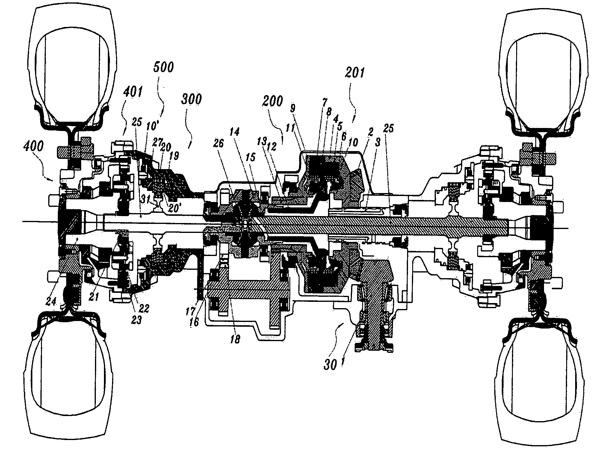
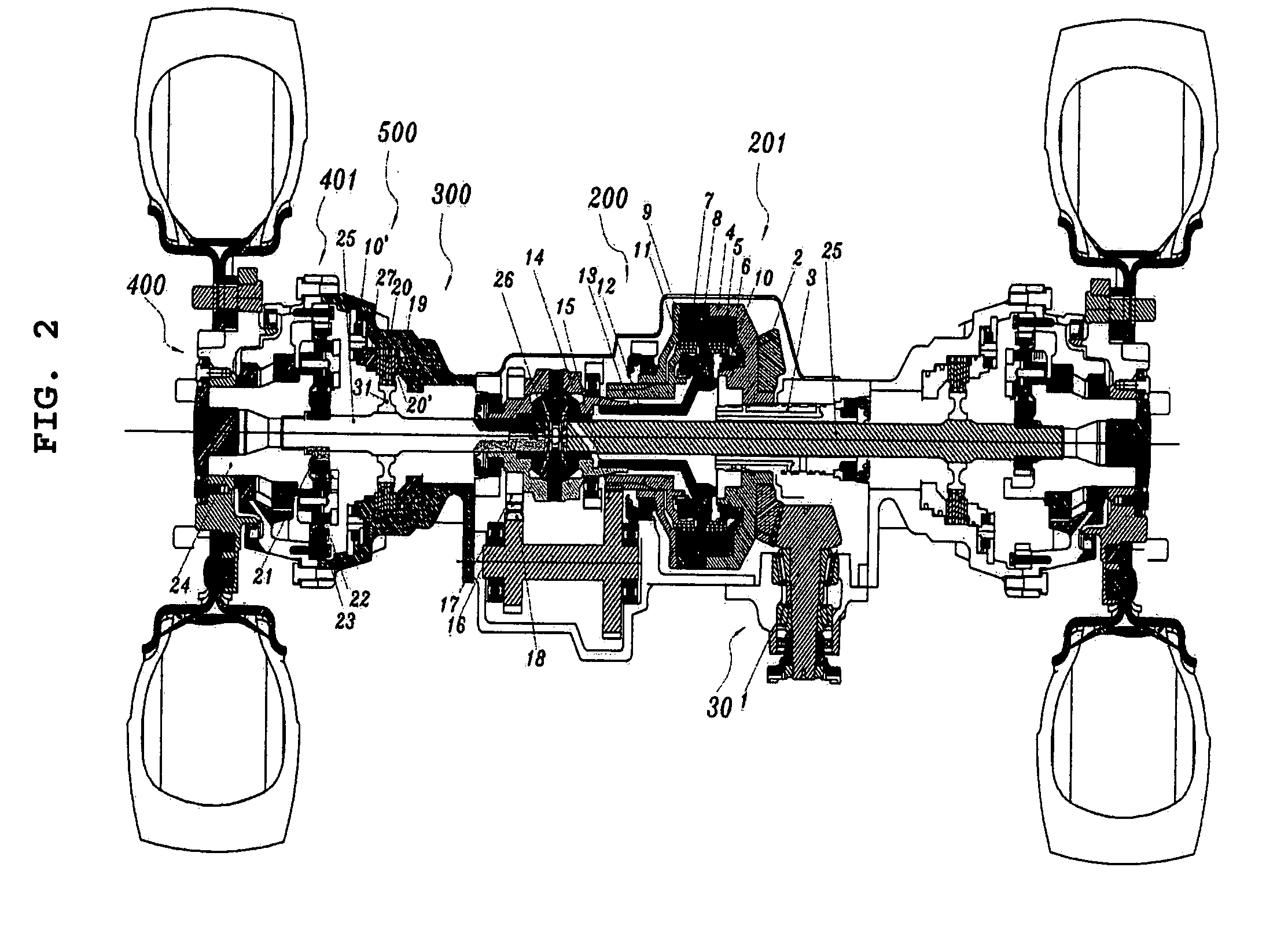
[0028] As shown in FIG. 2, a transmission in accordance with an embodiment of the present invention receives power which is transmitted at a right angle from a bevel gear section 30. A gear shift, that is, a speed change is implemented in a clutch unit 201. Speed-changed power is transmitted via a differential gear case 14 to a drive shaft 25, and a vehicle is driven through a reduction gear assembly 401 with speed-reduced power. FIG. 2 illustrates an entire construction and a power transmitting system of the transmission according to the present invention. Hereafter, detailed structures of the transmission will be described with reference to FIGS. 3 through 7.

[0029]FIG. 3 is a cross-se...


PUM


Abstract

A transmission for a vehicle. A rotation force generated in an engine is transmitted via a torque converter to an output shaft. Power of the output shaft is transmitted at a right angle at a bevel gear section that includes a bevel pinion gear and a bevel ring gear. The bevel ring gear transmits power to a clutch unit that includes forward and backward clutch sections to be connected to the bevel ring gear when a speed-change operation is implemented (for example, forward / backward gear shift operations). The clutch unit is connected to a differential gear case, which transmits power to a differential pinion gear and a drive shaft. The vehicle drivable through a reduction gear assembly that is mountable to an axle assembly.

Description

BACKGROUND OF THE INVENTION [0001] 1. Field of the Invention [0002] The present invention relates to a transmission which can be applied to heavy equipment such as a forklift and an excavator, a tractor, a special vehicle, and all powered vehicles and, more particularly, to a transmission having a simple construction, in which a clutch unit is separated from a wheel reduction gear assembly and positioned between a bevel gear and a differential pinion gear, whereby generation of noise and vibration is minimized, and the number of parts is decreased to reduce a weight and a manufacturing cost. [0003] 2. Description of the Related Art [0004] As well known to those skilled in the art, heavy equipment uses a hydraulic motor or an engine as its power source, and is divided into a wheel type and a crawler type, depending upon a shape of a wheel. [0005] Other than conventional vehicles, heavy equipment need not travel at a high speed and be frequently changed in its speed due to its operati...

Claims


Application Information

Patent Timeline
Patent Type & Authority Applications(United States)
IPC IPC(8): B60K17/02B60K17/04B60K17/06B60K17/08B60K17/28B60T1/06F16D25/0638F16D55/40F16D63/00F16H3/14F16H37/00F16H37/08
CPCB60K17/02F16H48/08B60K17/046B60K17/08
Inventor HAN, SEUNG-WOO
Owner JUNGHEINRICH AG
Why Eureka
Try Eureka