Apparatus for mechanically ventilating a patient

a technology for mechanical ventilation and apparatus, applied in the field of physical equipment, can solve the problems of clogging, causing infection, and affecting the use of such a tube, and achieve the effects of improving the quality of life, reducing the risk of dislodging, and reducing the use

Inactive Publication Date: 2005-12-01
BALBY BY DESIGN
View PDF17 Cites 18 Cited by
  • Summary
  • Abstract
  • Description
  • Claims
  • Application Information

AI Technical Summary

Benefits of technology

[0024] The inventive apparatus thereby simulates normal, physiologic breathing, eliminating the need for artificial airway maintenance and allowing each patient to achieve full mobility and thereby, normal existence.

Problems solved by technology

These machines provide lifesaving benefit, but are not without risks.
Use of such a tube carries complications such as difficulty in proper placement, risks of dislodging, clogging, or causing infection.
Additionally, the force with which each breath is delivered to the patient can lead to trauma to the lung tissue itself, including lung rupture or collapse.
However, such form of mechanical ventilation functions less than ideally because the gas cannot be directed solely into the lungs, but is rather forced into the back of the throat where the gas travels to both the lungs and stomach, the relative proportions of gas depending on the resistance of each pathway.
Furthermore, several noninvasive negative pressure ventilators require the patient to remain confined to bed (e.g., the “iron lung”), while others might allow the patient to sit up or be pushed in a wheelchair, but do not permit full mobility.

Method used


Image

  • Apparatus for mechanically ventilating a patient
  • Apparatus for mechanically ventilating a patient
  • Apparatus for mechanically ventilating a patient

Examples


Embodiment Construction

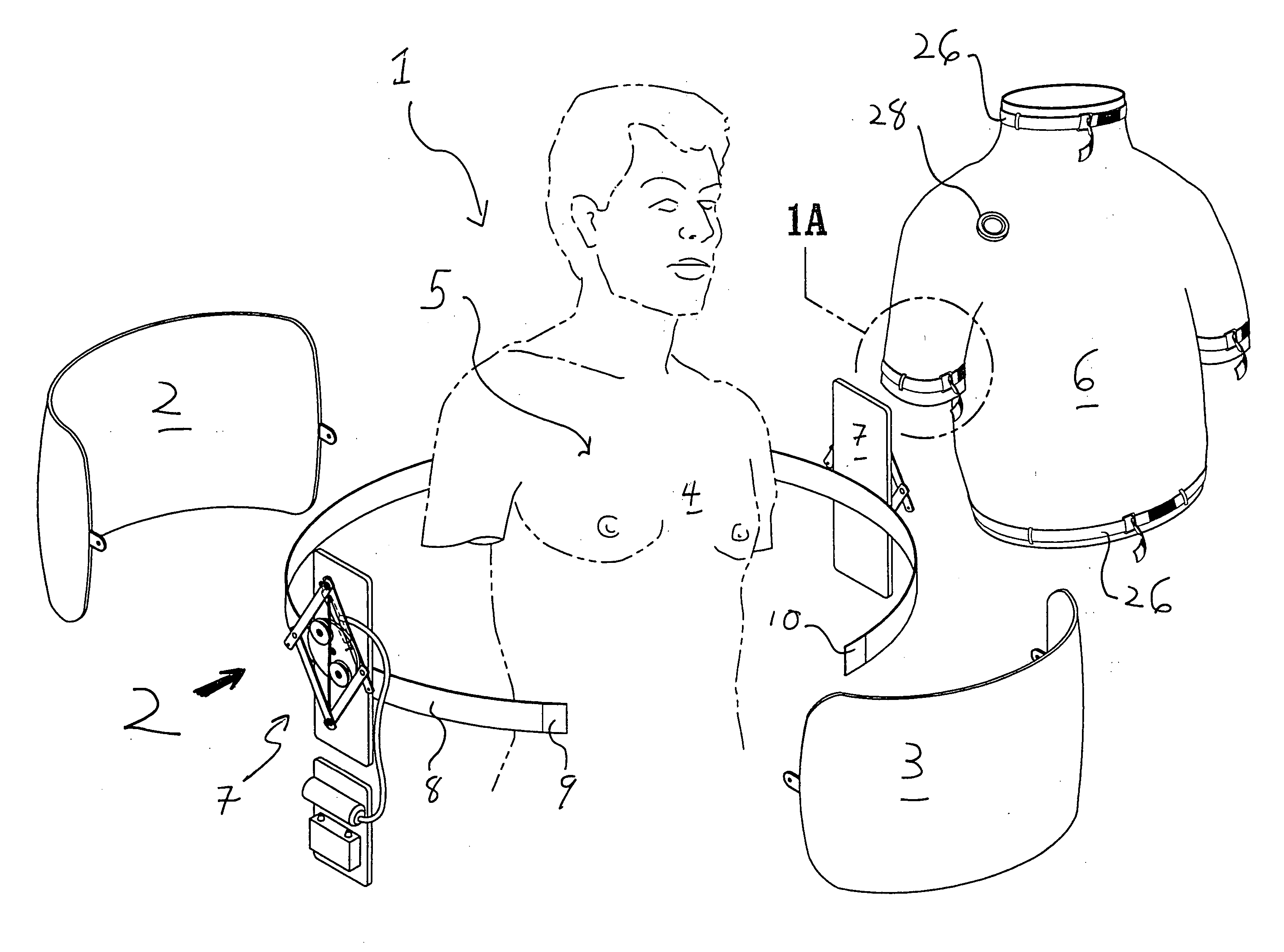
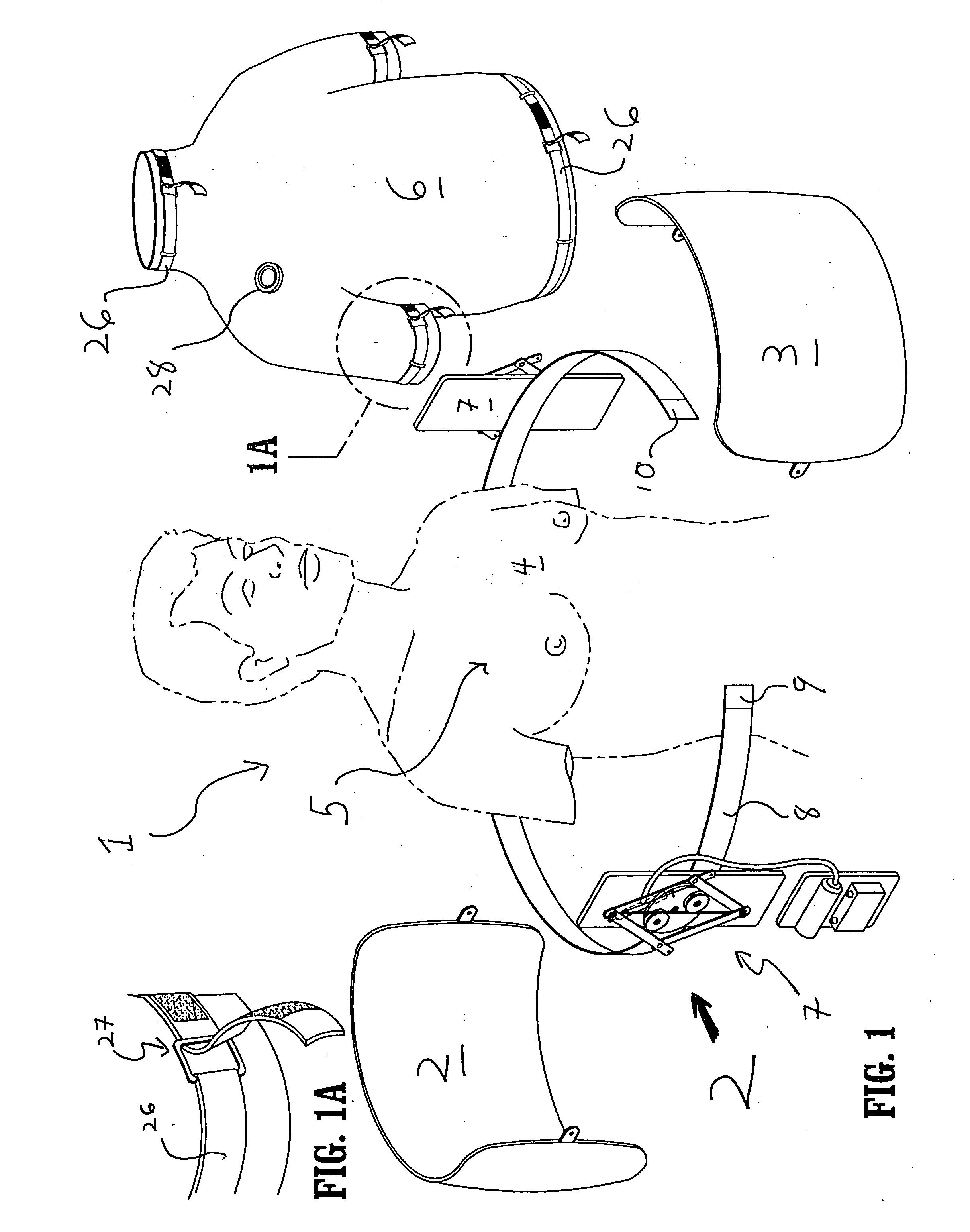
[0035] Referring to the drawings in which analogous components are denoted by analogous reference numerals or characters, the inventive apparatus 1 for mechanically ventilating a patient has two components 2 and 3 arranged to reciprocally move towards and away from one another. These components are positioned about the torso 4 of a patient, i.e., the chest cavity 5, and secured within an outer elastic shell 6, e.g., a vest or shirt, which can be formed of any suitable material such as spandex, polyester, etc. A preferred elastic garment that functions especially well as an air-tight elastic shell 6 in accordance with the present invention is a Nike Dri-Fit short sleeve shirt composed of 82% polyester and 18% spandex. This shirt was coated on the outer surface thereof with a thin layer of General Electric clear Silicone II 100% Window and Door silicone sealant, manufactured by GE Sealants and Adhesives, Huntersville, N.C. 28078, to enhance air-tightness.

[0036] The movable components...


PUM


Abstract

An apparatus for mechanically ventilating a patient is provided to have two separate components movably arranged with respect to one another within a flexible, air-tight covering fit about the torso of a patient. When the components move away from one another within the air-tight covering, negative pressure is generated which causes the patient to draw air into the lungs. Conversely, when the components stop moving away from one another within the air-tight covering, the patient's natural exhalation recoil takes over to allow the patient to expel the air from within the patient's lungs.

Description

BACKGROUND OF THE INVENTION [0001] The present invention is directed to a physical apparatus used to assist mechanically ventilating a patient. More specifically, the present invention provides non-invasive pressure changes outside a patient's chest wall, allowing mechanical ventilation without need for invasive endotracheal, orotracheal or tracheal intubation. [0002] Under normal physiological conditions, humans breathe using “negative pressure ventilation.” In other words, a negative intrathoracic pressure is created by contraction of the intercostal muscles (between the ribs), upward and outward expansion of the ribs, and downward movement of the muscular diaphragm separating the thorax from the abdomen. All these changes act to expand both lungs and thus create a negative intrathoracic pressure. The pressure change enables gas to move from the outside atmosphere, through the human air passages, and into the deepest areas of the human lung. The natural tendency of the lungs to co...

Claims


Application Information

Patent Timeline
Patent Type & Authority Applications(United States)
IPC IPC(8): A61H31/00A61H31/02
CPCA61H31/02Y10S601/06
Inventor BALDAUF, MARYBALDAUF, THOMAS
Owner BALBY BY DESIGN
Why Eureka
Try Eureka