Spinal stabilization system to flexibly connect vertebrae

a spinal stabilization and vertebrae technology, applied in the field of spinal stabilization systems allowing vertebrae to be flexible, can solve the problems of inability to lift heavy objects, inability to support load, and great discomfort of the spine, so as to prevent excessive motion, prevent the effect of excessive movement, and maintain a large range of spinal flexibility and mobility

Inactive Publication Date: 2005-12-01
MCBRIDE DUNCAN Q
View PDF14 Cites 295 Cited by
  • Summary
  • Abstract
  • Description
  • Claims
  • Application Information

AI Technical Summary

Benefits of technology

[0010] The present invention addresses the shortcomings of the prior art, by providing a system for posterior spinal stabilization that is simple, permits the user to retain a large range of spinal flexibility and mobility while preventing excessive motion and maintaining proper alignment, and is removable. The system is also universally applicable to all levels of the human spine.

Problems solved by technology

However, with a spinal injury, deformity or degeneration, even at a single disk level, the spine's ability to support load can be greatly compromised.
As a result, a person's spinal injury often leads to great discomfort when standing and an inability to lift heavy objects.
While spinal injuries such as herniated disks are currently treatable, certain treatments have undesirable results.
Therefore, a person who has undergone traditional vertebral fusion surgery will lose a degree of bending and twisting flexibility in the spine.
Also, the disks adjacent to the fused levels degenerate at an increased rate, often requiring extension of the fusion.
Furthermore the traditional fusion treatment (and its accompanying lack of flexibility) is essentially irreversible.
Pseudoarthrosis (or failed fusion) also is a risk of all attempts at achieving solid bony fusion, usually requiring reoperation.
Such procedures can weaken the spinal structure and result in post-operative increase in misalignments or reversal of normal lordosis.
Others have attempted to address the shortcomings of the traditional spinal fusion method, however, these attempts have had limited success and introduced further shortcomings.
However, these devices are complex, involving a large number of component parts.
This complexity would undesirably lead to long application and removal times and the need for extensive training by the applying surgeon.
Furthermore, the rigid alignment rods and other hardware would negatively impact flexibility (though not as much as the traditional vertebral fusion method).
These prior art devices address the traditional vertebral fusion's removability shortcoming but do not address the flexibility shortcomings.
Therefore, these devices restrict the wearer's range of mobility in bending and flexure.
Moreover, since the cables used in these devices are much less elastic than the cartilage, ligaments, and other soft tissues that define mobility in a healthy spine, these devices create an unnatural firm stop at the limits of movement

Method used


Image

  • Spinal stabilization system to flexibly connect vertebrae
  • Spinal stabilization system to flexibly connect vertebrae
  • Spinal stabilization system to flexibly connect vertebrae

Examples


first embodiment

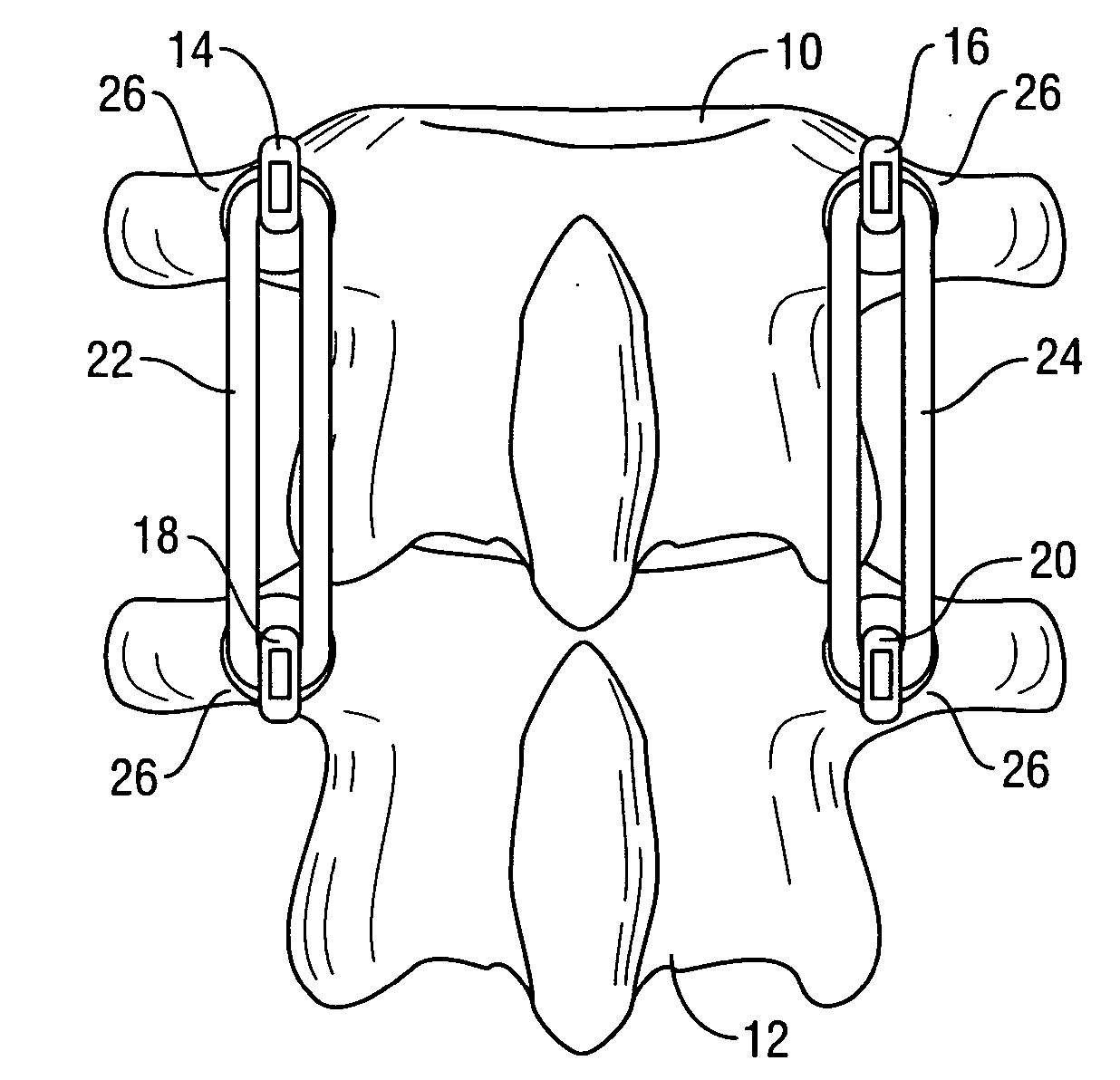
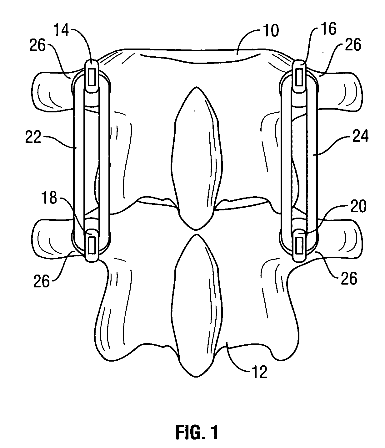
[0028] As is evident from the first embodiment in FIG. 1, the system of the present invention flexibly attaches two vertebrae 10, 12 while allowing the vertebrae to move relative to each other to the extent of the elasticity of the elastic bands 22, 24, thereby allowing the wearer to have a high degree of mobility and flexibility. Further, the few component parts of the present invention facilitate ease of application. FIG. 1 depicts the system of the present device as applied to two lumbar vertebrae 10, 12, with the anchor hooks 14, 16, 18, 20 attached to the vertebrae 10, 12 at the pedicle location 26. However, it should be recognized that the system of the present invention may be applied to any two adjacent vertebrae along the length of the spine. The location of the anchor hooks, however would vary from lateral masses in the cervical vertebrae to pedicles 26 in the thoracic and lumbar vertebrae.

second embodiment

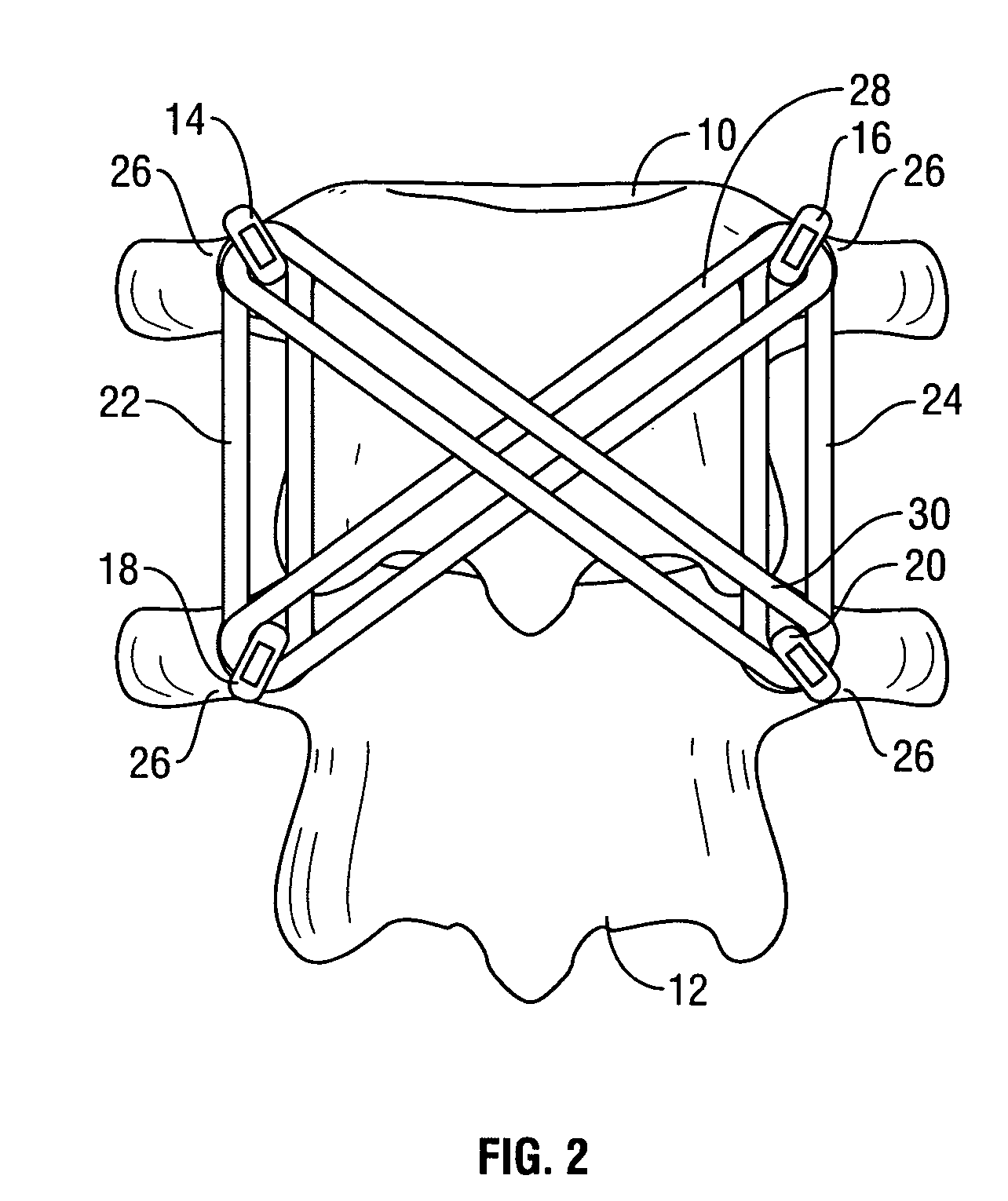
[0029] the present invention is depicted in FIG. 2. The second embodiment flexibly connects two vertebrae 10, 12 while providing enhanced promotion of alignment and preventing listhesis. The second embodiment comprises all of the elements of the first embodiment, as depicted in FIG. 1, and further comprises: a third elastic band 28 retained by the left anchor hook 14 in the upper vertebra 10 and the right anchor hook 20 in the lower vertebra 12; and a fourth elastic band 30 retained by the right anchor hook 16 in the upper vertebra 10 and the left anchor hook 18 in the lower vertebra 12.

[0030] The second embodiment of the present invention allows flexibility and mobility while enhancing promotion of alignment. Further, the second embodiment of the present invention has very few component elements as compared with complex rod-based systems of the prior art. As with the first embodiment of the invention, the second embodiment may be applied, by varying attachment locations for the anc...


PUM


Abstract

A surgically implanted spinal stabilization system uses posterior anchor hooks attached to vertebrae to retain elastic bands to retain flexibility and mobility while maintaining alignment and preventing excessive motion and deformity. The elastic bands may parallel the longitudinal axis of the spine, or, for enhanced promotion of alignment, they may also arranged in a diagonally crossing configuration. Multi-level fixation can be achieved using the spinal stabilization system with longer elastic bands. A method of applying the spinal stabilization system using an elastic band application tool facilitates simple, rapid application of the system to a patient.

Description

BACKGROUND OF THE INVENTION [0001] 1. Field of the Invention [0002] The present invention relates to devices used to provide spinal stabilization and more particularly to systems for spinal stabilization allowing flexibility of the vertebrae. [0003] 2. Description of Related Art [0004] The human spine is comprised of 33 stacked vertebrae extending from the base of the skull to the tailbone with cartilaginous disks sandwiched between each two adjacent vertebrae providing a cushion and easing movement of the vertebrae relative to each other. In a healthy spine, this interconnected arrangement of vertebrae and disks supports loads while remaining highly flexible—since each vertebra can move with respect to the adjoining vertebrae, the spine can bend and twist to a remarkable degree. However, with a spinal injury, deformity or degeneration, even at a single disk level, the spine's ability to support load can be greatly compromised. As a result, a person's spinal injury often leads to gr...

Claims


Application Information

Patent Timeline
Patent Type & Authority Applications(United States)
IPC IPC(8): A61B17/58A61B17/70A61B17/88
CPCA61B2017/7073A61B17/7022
Inventor MCBRIDE, DUNCAN Q.
Owner MCBRIDE DUNCAN Q
Why Eureka
Try Eureka