Intracorporeal occlusive device and method

a technology of intracorporeal occlusion and occlusion chamber, which is applied in the field of intracorporeal occlusion devices, can solve the problems of significant medical problems to the population, devastating consequences for patients, and high risk of procedures, and achieve the effect of preventing the egress of the space filling devi

Inactive Publication Date: 2005-12-01
MARKS MICHAEL P
View PDF78 Cites 71 Cited by
  • Summary
  • Abstract
  • Description
  • Claims
  • Application Information

AI Technical Summary

Benefits of technology

[0006] One preferred embodiment of the invention is an intracorporeal space filling device which has an elongate tubular shell with a lumen disposed within the shell. The lumen is in fluid communication with a first port in a first end of the shell, and a second port in a second end of the shell. A transmutable material is disposed within the lumen of the shell substantially filling the lumen. The transmutable material has properties which enable transformation from a non-rigid state to a substantially rigid state within a patient's body. The transmutable character of the transmutable material allows for a space filling device that is soft and flexible at the time of deployment into an intracorporeal cavity and rigid and substantially incompressible after being converted to a rigid state. Such a device can conform readily to the varied morphology of intracorporeal cavities and transmute to a substantially rigid mass upon activation or hardening of the transmutable material so as to be resistant to compression and reforming due to vascular or other types of pressures within a patient's body.
[0009] In a preferred embodiment, the elongate tubular shell is configured to have an outer surface which is self adhering to create attachment points from contact point upon activation of the self adhering outer surface. Contact points along the length of the space filling device inevitably occur when the device is deployed within an intracorporeal cavity or channel and the space filling device assumes a folded or convoluted space filling configuration. The folded or convoluted space filling configuration may be due to the confinement of the void or channel, a secondary shape assumed by the device in a relaxed state, or both. The creation of attachment points results in a more rigid and stable space filling mass that is resistant to compaction and reforming.
[0013] Embodiments with beads of exposed transmutable material can be cross-linked or bonded to adjacent beads which are in contact at the time of transmutation at a desired site within a patient's body. Adjacent beads in contact while deployed within a desired location within a patient can adhere or bond together and create attachment points upon transmutation of the transmutable material. The attachment points create a more stable and rigid mass than would be achieved by transmutation of the beads without attachment points.
[0016] During deployment of a space filling device, a blocking balloon may be deployed adjacent the opening of an intracorporeal void and distal end of a microcatheter disposed within the void prior to distally advancing the space filling device from the distal end of the microcatheter into the cavity. The blocking balloon prevents egress of the space filling device from within the cavity during deployment of the device.

Problems solved by technology

Cerebral aneurysms and other cerebral vascular abnormalities present a significant medical problem to the population of the United States.
It is estimated that the number of ruptured intracranial aneurysms yearly is in the tens of thousands, often with devastating consequences for the patient.
Because of the invasive nature of the procedure and the vulnerability of the brain tissue surrounding the aneurysm, this procedure carries a high degree of risk with concomitant mortality and morbidity rates.
This risk is particularly high when the aneurysm has ruptured prior to the surgical intervention.
However, the coils are hollow bodies, often made of relatively soft metals which are subject to compaction due to the pressure exerted on the deployed coils by the patient's blood flow.
Compaction and reforming of the coils leaves them susceptible to dislodging and being displaced within the patient's vasculature, with the potential for causing distal embolization.
In addition, compaction of the coils into the dome of the aneurysm or blood clot surrounding the coils can lead to reappearance and regrowth of the aneurysm.
Finally, aneurysms with wide necks having a dome to neck dimension ratio of less than 2 to 1 often do not provide a morphology conducive to retention of coils within the aneurysm.
When the space filling device is deployed in an intracorporeal cavity and assumes a folded, bunched or convoluted configuration due to a secondary shape of the elongated longitudinal member or the natural confinement of the cavity, inevitably, certain portions of the space filling device will make physical contact with other portions of the device.
The cross-linking or bonding of the device at attachment points results in a rigid mass which is resistive to compression and reforming.

Method used


Image

  • Intracorporeal occlusive device and method
  • Intracorporeal occlusive device and method
  • Intracorporeal occlusive device and method

Examples


Embodiment Construction

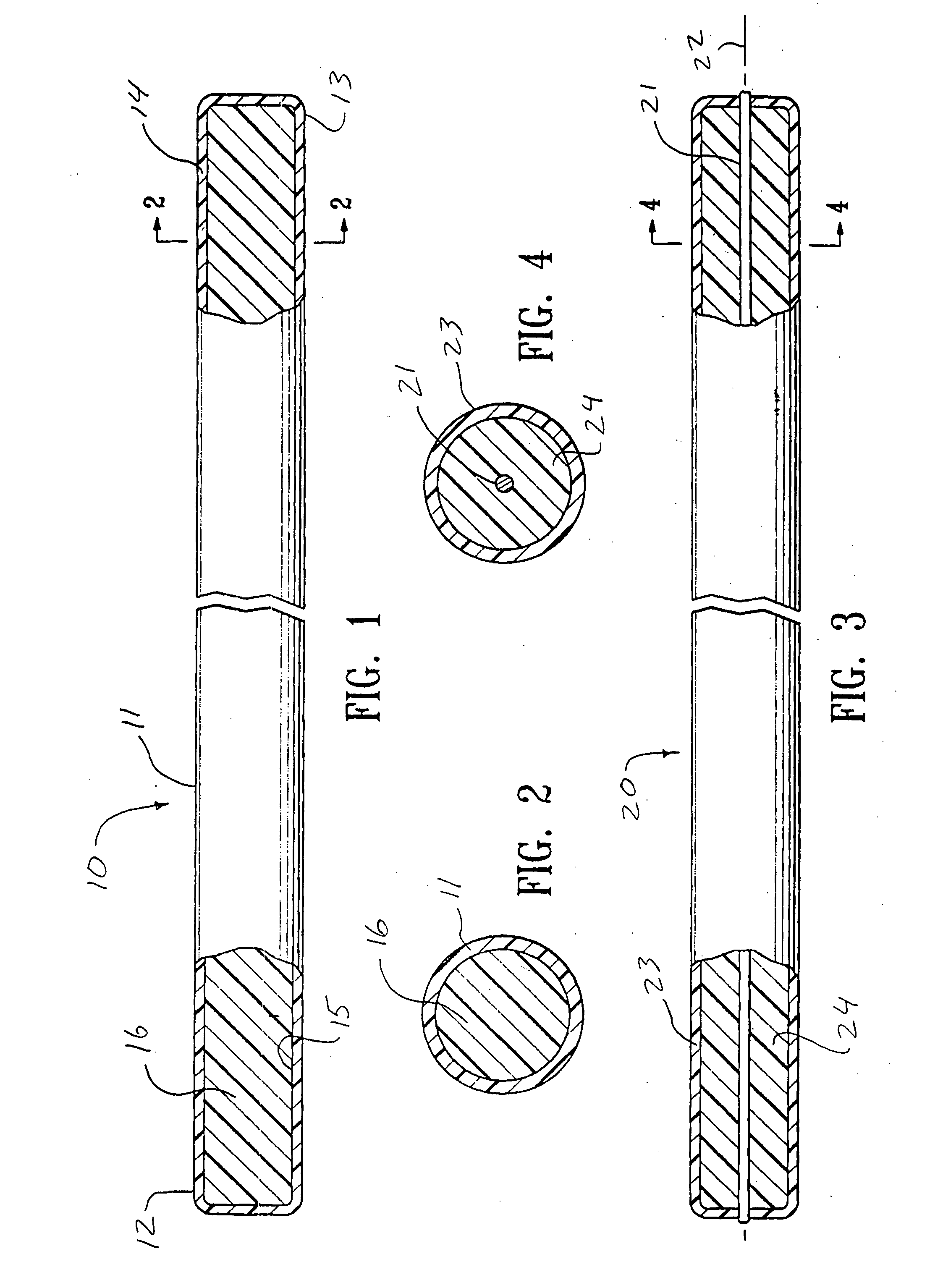
[0042]FIG. 1 illustrates an intracorporeal space filling device 10 having features of the invention. The intracorporeal space filling device 10 has an optional elongate tubular shell 11 with a first end 12 and a second end 13, the elongate shell being formed of a wall material 14. There is a lumen 15 disposed within the elongate tubular shell 11 which has transmutable material 16 disposed therein.

[0043] The elongate tubular shell 11 can be made from a variety of materials including metals and polymers. Suitable metals for the elongate tubular shell include stainless steel, NiTi, gold, platinum, tantalum, palladium, alloys thereof and the like. If a metal or other rigid material is used, methods such as forming slots or grooves in the wall material of such an elongate tubular shell may be used to achieve a desired longitudinal flexibility of the elongate tubular shell 11. Suitable polymers for the elongate tubular shell 11 can include polyurethane, polyethylene, nylon, polyimide, po...


PUM


Abstract

An intracorporeal space filling device and a delivery system and method for using the device is disclosed. The space filling device is preferably configured for percutaneous delivery from a peripheral conduit of a patient. The space filling device has an elongated tubular or interconnected bead structure which may have a transmutable material disposed within it. The transmutable material can be altered from a non-rigid state to a rigid state by the application of various types of energy or by other suitable means. The space filling device can be positioned by a delivery system and detached from the delivery system after desired positioning is achieved.

Description

[0001] This application is a continuation of application Ser. No. 10 / 106,511, filed Mar. 25, 2002 which is a divisional application of application Ser. No. 09 / 324,987, filed Jun. 2, 1999. The disclosures of these prior applications are incorporated in their entirety herein by this reference.BACKGROUND [0002] The present invention is generally directed to occlusion devices and, more specifically, to intracorporeal occlusion devices which can be used to treat a patient's blood vessels, intracorporeal conduits or other portions of a patient's body. A preferred embodiment can be used to treat intracranial aneurysms, arteriovenous fistulas, and other abnormalities within the cerebral vasculature. [0003] Cerebral aneurysms and other cerebral vascular abnormalities present a significant medical problem to the population of the United States. It is estimated that the number of ruptured intracranial aneurysms yearly is in the tens of thousands, often with devastating consequences for the pat...

Claims


Application Information

Patent Timeline
Patent Type & Authority Applications(United States)
IPC IPC(8): A61B17/12A61B17/22A61M29/00
CPCA61B17/12022A61B2017/12077A61B17/12113A61B17/12136A61B17/12145A61B17/12163A61B17/12195A61B2017/00477A61B2017/00867A61B2017/12063A61B2017/22068A61B2017/22069A61M2025/1052A61B2017/12068A61B2017/12072A61B17/12109A61B17/1214
Inventor MARKS, MICHAEL P.ROSS, MICHAEL
Owner MARKS MICHAEL P
Why Eureka
Try Eureka