
Reciprocal bi-directional table saw

Inactive Publication Date: 2005-12-08
CHIEN CHUN JEN
View PDF17 Cites 23 Cited by
  • Summary
  • Abstract
  • Description
  • Claims
  • Application Information

AI Technical Summary

Benefits of technology

[0007] Another purpose of the present invention is to provide a table saw that fast and firmly clamps a work piece in position and allows the adjustment of the cutting amount or dimension of the work piece for an easier and convenient operation of the cutting process.
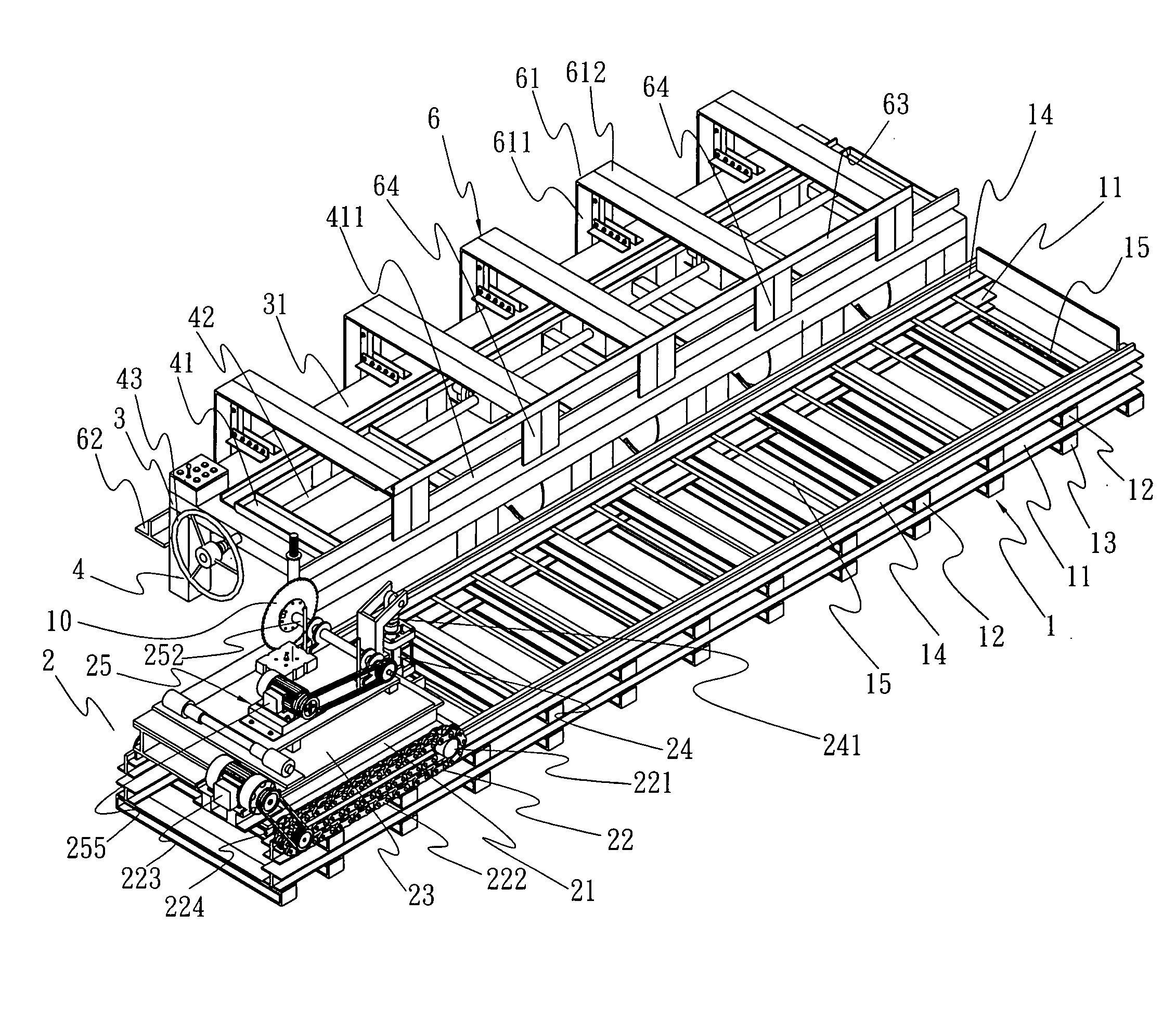
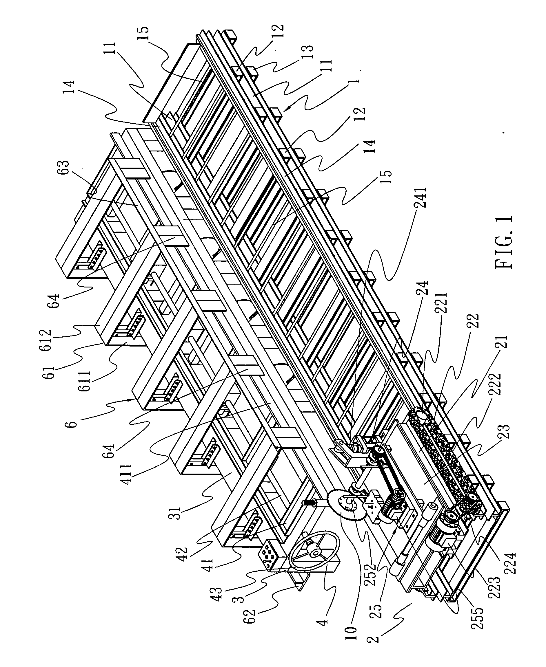
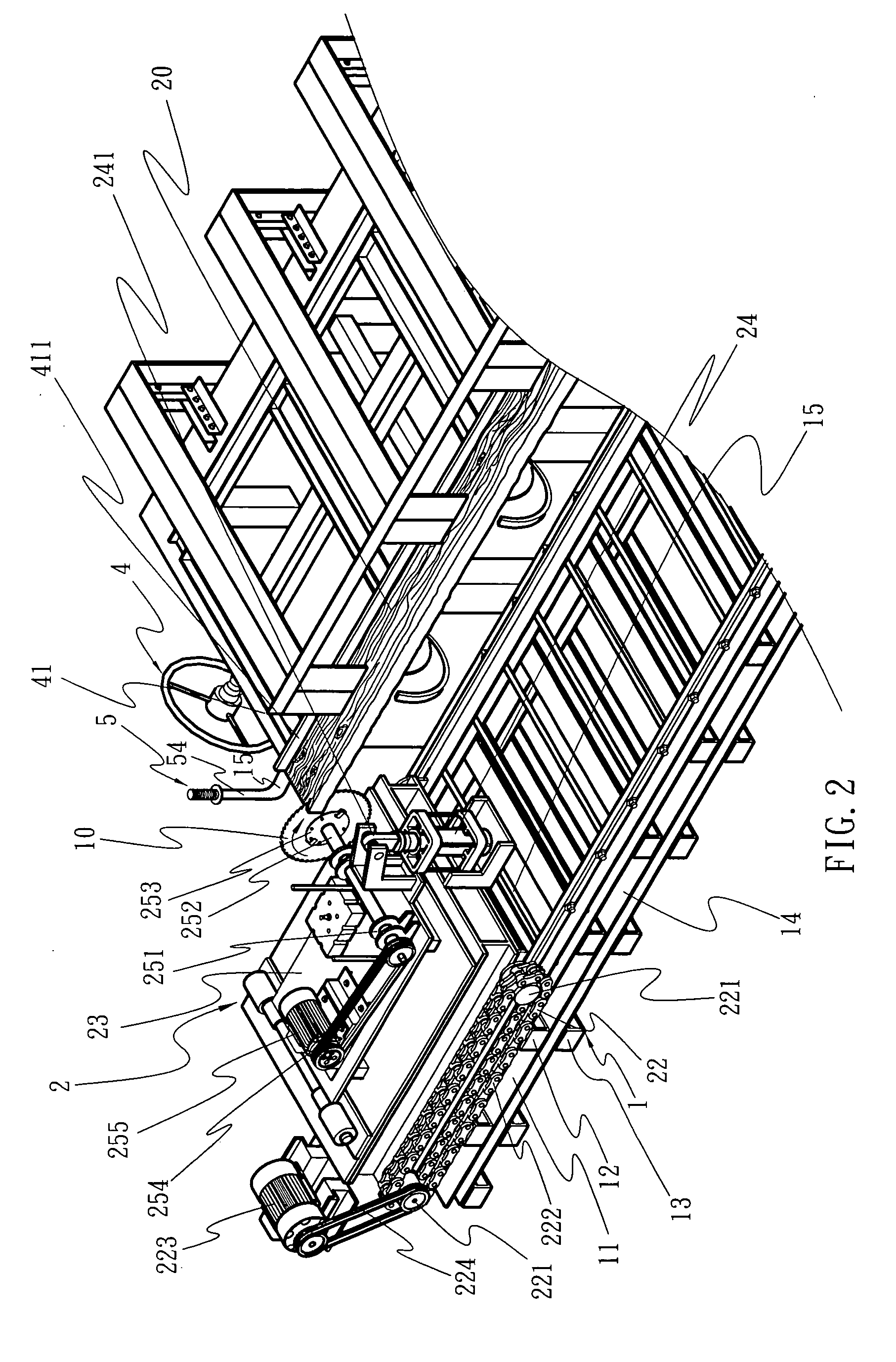
[0008] To achieve the purpose, the table saw includes a sawing table, a deck to secure the work piece in position. Wherein, the deck relates to a console that holds the work piece in position and is capable of adjusting the cutting amount or dimension of the work piece. The sawing table provided by the side of the deck includes a horizontal runway and a cutting process unit that reciprocally and automatically travels on the runway. The automatic travel device is each provided on both sides of a seat plate of the cutting process unit, and a saw blade holder with its one end pivoted to be controlled by a plunger member to ascend or descend is provided on the seat plate. A circular saw blade and a device required to drive the saw blade are provided on the saw blade holder. Accordingly, both of the relative cutting angle and position between the circular saw blade and the work piece can be adjusted during the reciprocal trips of the cutting process unit to execute the reciprocal cut on the work piece in both direction to provide the cutting results that yield precise dimensioning of the work piece, efforts saving in the cutting and upgraded production rate.

Problems solved by technology

However, this type of sawing machine consumes a lot of efforts and is applicable only to process wood in smaller size.
It fails to handle larger and heavier logs or excessively long boards.
Therefore, such fixed type of table saw has a limited scope of application.
However, this type of table sawing machine for being limited to the relatively optimal cutting angle between the circular saw blade and the wood has to be fixed in position; accordingly it travels to cut only in one direction and is prevented from cutting while on its returning trip.

Method used


Image

  • Reciprocal bi-directional table saw
  • Reciprocal bi-directional table saw
  • Reciprocal bi-directional table saw

Examples


Embodiment Construction

[0025] Referring to FIGS. 1, 2, and 3, a reciprocal bi-directional table saw relates to one that has a work piece clamped in position and a circular saw blade 10 is used to cut the work piece reciprocally in two directions. When applied to cut a board or similar work piece, a preferred embodiment of the present invention is essentially comprised of a table and a deck to secure the work piece in position. Wherein, the table related to a mechanism for the circular saw blade 10 in linear movement to execute the sawing work is comprised of a runway 1 and a cutting process unit 2. Wherein, the runway 1 as illustrated in FIG. 1, bears the cutting process unit 2 and guides it to travel back and forth. The runway 1 is comprised of multiple rails. A strip rail base 11 is each provided on both sides of a lower deck of the runway. Multiple ties 12, 13 are respectively provided on and beneath the rail base 11. Both rail bases 11 are arranged in parallel to each other and separated from each oth...


PUM

PropertyMeasurementUnit
Circumferenceaaaaaaaaaa

Abstract

A reciprocal bi-directional table saw including a cutting table and a deck to secure a work piece in place; the table including a horizontally provided runway and a cutting process unit that automatically travels back and forth on the runway; an automatic travel device being each provided on both sides of a seat plate provided to the cutting process unit; a saw blade elevates as controlled by a plunger having one side pivoted to the seat plate; a circular saw blade and a device to drive the circular saw blade being provided on the saw blade holder for the table saw to reciprocally execute the cutting on the work piece to achieve precise process of the work piece and upgrade the production rate.

Description

BACKGROUND OF THE INVENTION [0001] (a) Field of the Invention [0002] The present invention is related to a reciprocal bi-directional table saw, and more particularly, to one with a work piece clamped in position while a circular saw blade travels to cut for the circular saw to elevate. [0003] (b) Description of the Prior Art [0004] Table sawing machines generally available in the market are available in many types. Some are dedicated depending on function for cutting specified materials, such as metal, wooden, cement or building materials; while others vary according to type and assembly of saw blade such as band saw, saw blade, horizontal or vertical assembly). In addition, there are also sawing machines classified depending on whether the work piece is fixed in place or not. Within, taking the table saw to cut handle materials for instance, the saw blade is usually fixed in position while the work piece is moved close to the saw blade for cutting. The operator has to manually push...

Claims


Application Information

Patent Timeline
IPC IPC(8): B23D7/00B23D19/00B23D33/02B23D45/04B23D47/04B26D1/14B26D5/00B27B5/04B27B5/20B27B19/00B27B29/00
CPCB23D45/046B23D47/04B27B29/00B27B5/206B27B5/207B27B5/04Y10T83/7684
Inventor CHIEN, CHUN-JEN
Owner CHIEN CHUN JEN
Learn More