Pneumatic tire
- Summary
- Abstract
- Description
- Claims
- Application Information
AI Technical Summary
Benefits of technology
Problems solved by technology
Method used
Image

Examples
example
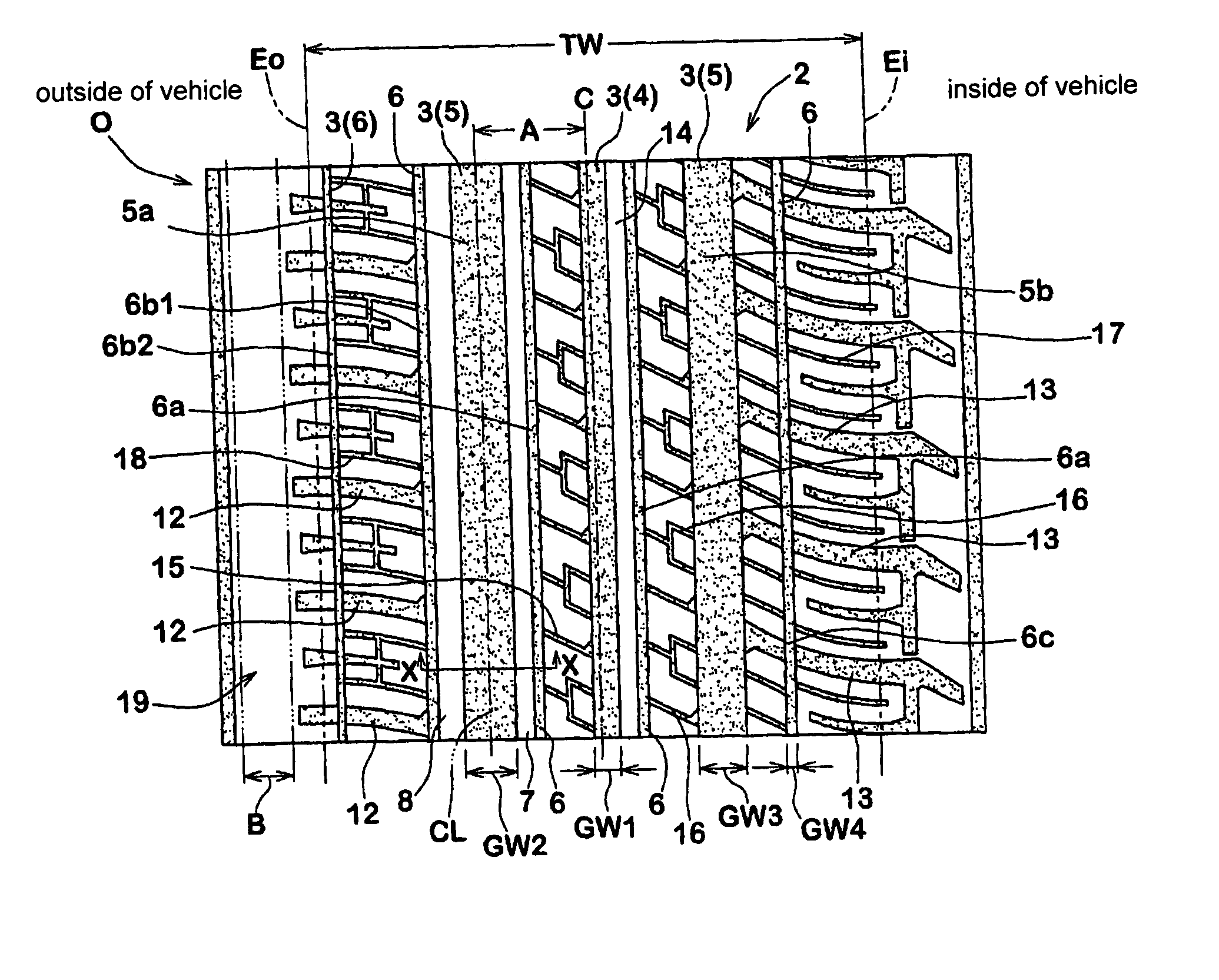
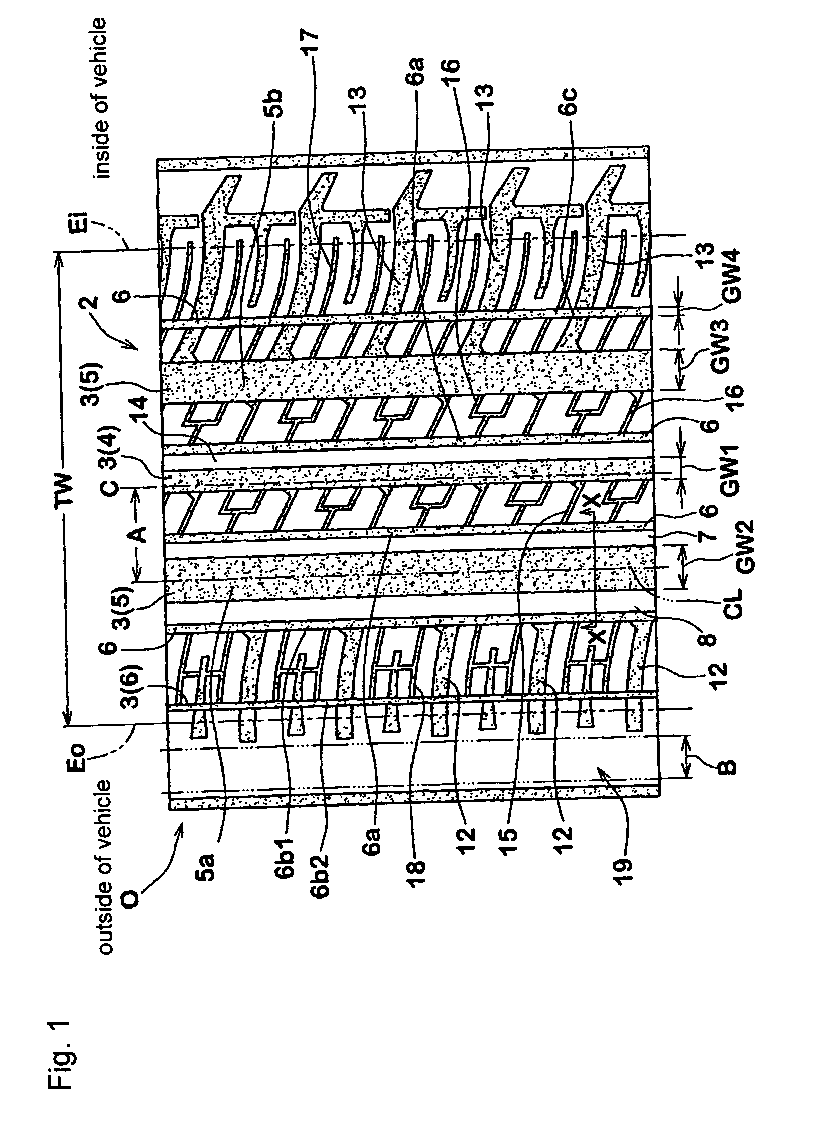
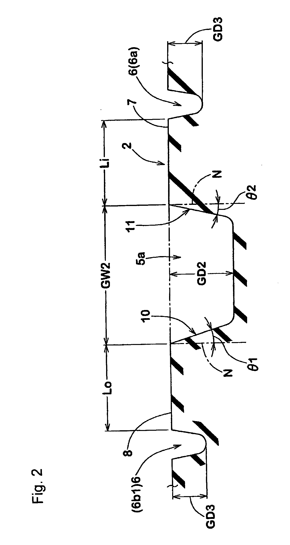
[0040]
Tread grounding width TW 142 mmGroove width GW1 of central groove 7.5 mm [5.3%]Groove depth of central groove 8.0 mmGroove width GW2 of outer broad width groove14.0 mm [9.9%]Groove depth of outer broad width groove 8.0 mmDistance A 32 mm [22.5%]Groove width GW3 of inner broad width groove12.0 mm [8.5%]Groove depth of inner broad width groove 8.0 mmGroove width GW4 of narrow groove 2.0 mm [1.4%]Groove depth of narrow groove 3.0 mmRatio {(GW1 + GW2 + GW3 + 5 × GW4) / TW29.2%Outer rib width Lo 8.0 mm [5.6%]Inner rib width Li 6.5 mm [4.6%]Inclination angle of groove wall θ112°Inclination angle of groove wall θ210°Groove width of outer lateral groove 4.5 mm
[0041] Numeric values within brackets [ ] indicate ratios (%) with respect to the tread grounding width TW. Methods for testing were as follows. In the comparative examples 1 and 2, the width of the land portion on both sides of the outer broad width groove was defined to be 25 mm.
Wet Performance
[0042] A vehicle mounted with sa...
PUM
 Abstract
Description
Claims
Application Information
 - Generate Ideas
- Intellectual Property
- Life Sciences
- Materials
- Tech Scout
- Unparalleled Data Quality
- Higher Quality Content
- 60% Fewer Hallucinations
Browse by: Latest US Patents, China's latest patents, Technical Efficacy Thesaurus, Application Domain, Technology Topic, Popular Technical Reports.
© 2025 PatSnap. All rights reserved.Legal|Privacy policy|Modern Slavery Act Transparency Statement|Sitemap|About US| Contact US: help@patsnap.com