Sealant dispenser and control method thereof

a technology of sealant dispenser and control method, which is applied in the direction of program control, separation process, instruments, etc., can solve the problems of limited use of highly viscous sealant, deterioration of screen uniformity over the entire screen of the lcd, and limited use of sealant dispenser, so as to increase the response speed of the sealant and control the dispensing amount. , the effect of accurate control

Active Publication Date: 2005-12-08
TOP ENG CO LTD
View PDF7 Cites 14 Cited by
  • Summary
  • Abstract
  • Description
  • Claims
  • Application Information

AI Technical Summary

Benefits of technology

[0025] Still another object of the present invention is to provide a sealant dispenser featuring an accurate control over the dispensing position and dispensing amount of a sealant by increasing the response speed of a sealant to be dispensed, and a control method thereof.

Problems solved by technology

This is because if the cell gap is not uniform or if liquid crystal is applied too much or insufficiently, the screen uniformity over the entire screen of an LCD will be deteriorated.
However, the related art sealant dispenser has the following problems.
In that light, the related art dispenser requires a high pressure for discharging the sealant, and the usage of a highly viscous sealant was limited.
Secondly, according to the related art sealant dispenser, the nozzle is installed on the lower portion of the bracket, so that there is a great distance between the position on the substrate where the sealant is discharged and the position on the substrate where a laser beam is reflected.
Therefore, the distance sensor cannot get an accurate a vertical distance from the point to which the sealant is actually discharged to the nozzle.
Thirdly, since the flow path of the sealant in the related art sealant dispenser is in “L” shape, the sealant is relatively slowly discharged.

Method used


Image

  • Sealant dispenser and control method thereof
  • Sealant dispenser and control method thereof
  • Sealant dispenser and control method thereof

Examples


Embodiment Construction

[0054] Reference will now be made in detail to the preferred embodiments of the present invention, examples of which are illustrated in the accompanying drawings.

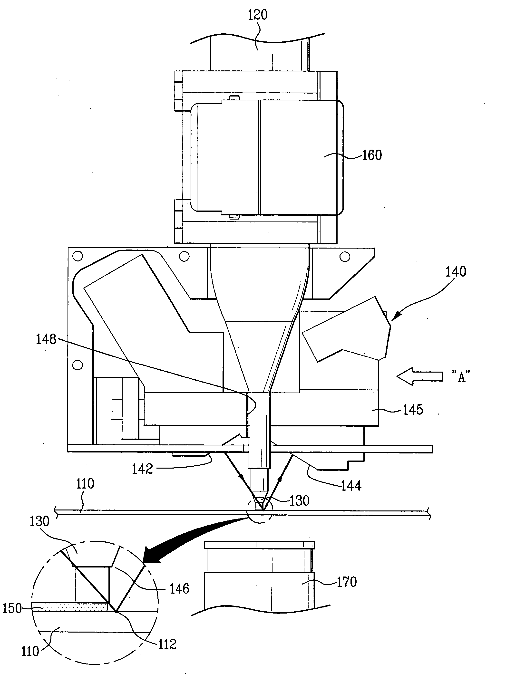
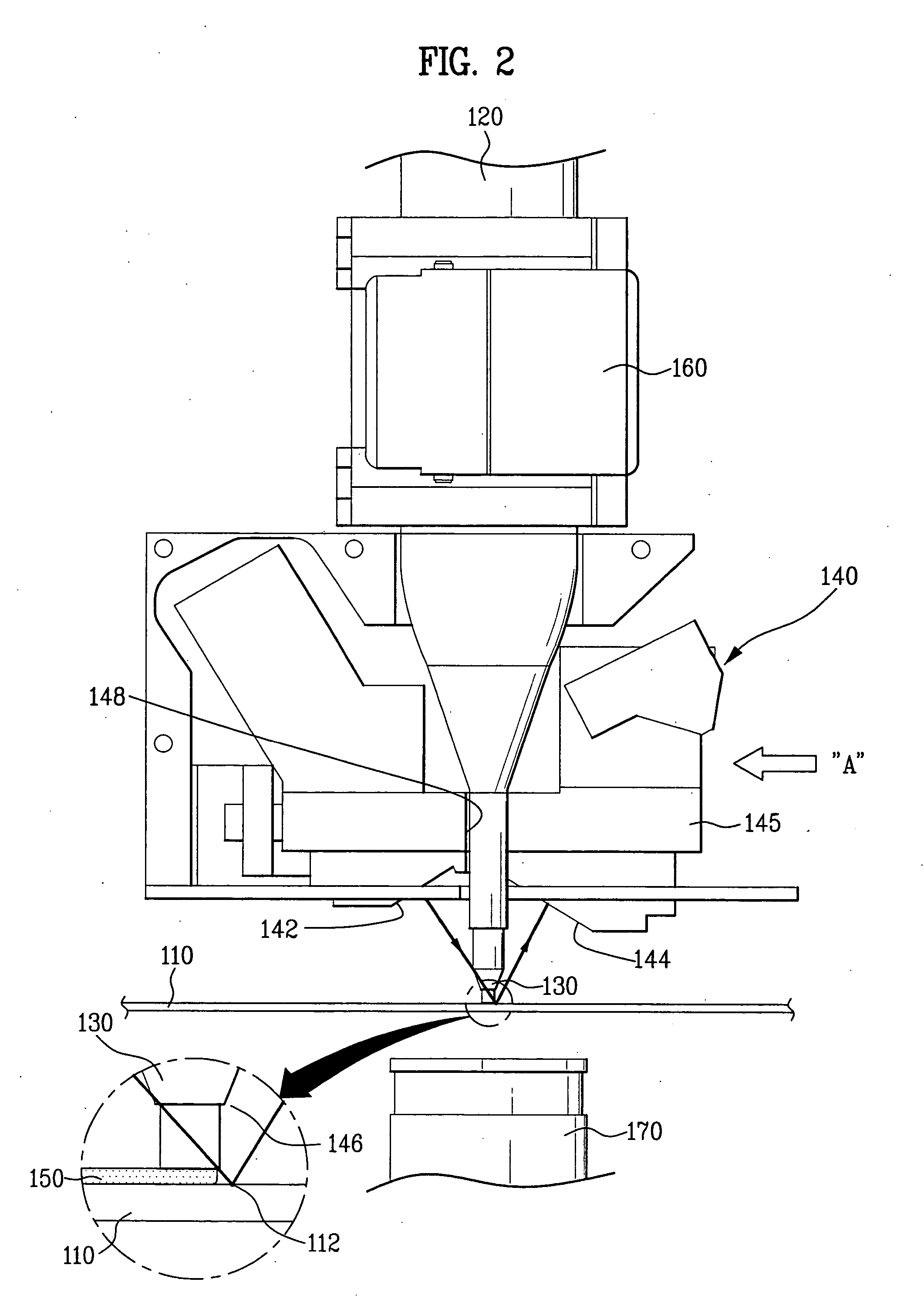
[0055]FIG. 2 is a front view illustrating key elements of a sealant dispenser according to the present invention; FIG. 3 is a side view of a key element taking in the direction of arrow A in FIG. 2; and FIG. 4 illustrates a detected position of a distance sensor which is photographed by a position detecting sensor, and a location of a nozzle.

[0056] Referring to FIG. 2 to 4, the sealant dispenser of the present invention includes a nozzle 130 for discharging a sealant while making a relative motion to a substrate 110 mounted on a stage, a syringe 120 coupled to the nozzle 130, for storing the sealant, and a distance sensor 140 installed on both sides of the lower portion of the syringe 120, for measuring a vertical distance from the principal plane of the substrate 110 to an outlet of the nozzle 130.

[0057] The syringe 120...


PUM

PropertyMeasurementUnit
vertical distanceaaaaaaaaaa
distanceaaaaaaaaaa
horizontal distanceaaaaaaaaaa

Abstract

Disclosed is a sealant dispenser for more precisely dispensing a sealant onto a substrate, and a control method thereof. The sealant dispenser includes a stage on which a substrate is mounted; a nozzle for dispensing a sealant while making a relative motion with the substrate; a syringe coupled to the nozzle, for storing the sealant; and a distance sensor installed on both sides of a lower portion of the syringe, for measuring a vertical distance between a principal plane of the substrate and an outlet of the nozzle. According to the principles of the present invention, because the nozzle and the syringe have substantially the same central axis, the response speed of the sealant to be dispensed is increased and the start point and the end point of paste pattern are more precisely dispensed. Also, by minimizing the distance between the nozzle and a measuring point provided by the distance sensor, it becomes possible to dispense the sealant at higher precision.

Description

RELATED APPLICATION [0001] This application claims the benefit of the Korean Patent Application No. P2004-0033395, filed on May 12, 2004, which is hereby incorporated by reference as if fully set forth herein. BACKGROUND OF THE INVENTION [0002] 1. Field of the Invention [0003] The present invention relates in general to a sealant dispenser, and more specifically, to a sealant dispenser for more precisely applying (or dispensing) a sealant onto a substrate, and a control method thereof. [0004] 2. Background of the Related Art [0005] In general, liquid crystal display (LCD) is lighter and smaller by volume than a traditional image display device using cathode-ray tube (CRT). Therefore, making great strides in recent years, LCD has been widely applied in many display devices, such as computer monitors and TVs. [0006] In case of the LCD, there is a certain space between an upper substrate and a lower substrate, and the space is filled with liquid crystal. In order for the LCD to perform...

Claims


Application Information

Patent Timeline
Patent Type & Authority Applications(United States)
IPC IPC(8): G02F1/13B05C5/00B05C5/02B05C11/00B05C11/10B05D1/26B05D3/00B65D88/54B67D3/00B67D7/06G01F11/06G01F11/30G01F11/36G01F11/42G02F1/1339
CPCB05C5/0216G05B2219/49362G05B2219/45238B05C11/10B05C11/1018A61L9/00A47B88/40B01D53/323
Inventor AHN, MAN HOKIM, JOON YOUNG
Owner TOP ENG CO LTD
Why Eureka
Try Eureka