Cone rock crusher

a crusher and cone technology, applied in the field of rock crushers, can solve the problems of increasing the time required to produce a desired amount of saleable rock, increasing the cost of saleable rock products, and prior art lubrication systems, so as to improve the quality, increase the quantity of end products, and improve the efficiency and economic effect of machine operation

Inactive Publication Date: 2005-12-08
INNOTECH SOLUTIONS
View PDF18 Cites 50 Cited by
  • Summary
  • Abstract
  • Description
  • Claims
  • Application Information

AI Technical Summary

Benefits of technology

[0007] The present invention is an improved cone-style rock crusher that will improve the quality and increase the quantity of the end products, while providing an overall more efficient and economical machine to operate. The rock crusher may be adjusted for varying rock crushing specifications, including different speeds, throws, and liners.
[0008] The rock crusher comprises a frame that supports a crusher bowl, a crusher head and a shaft, with the shaft being secured to the crusher head. The crusher head and the shaft are spaced apart and located within the crusher bowl. A domed feed plate may be secured onto the crusher head for assistance in secondary rock crushing processes. The shaft is driven by an electric drive system, which allows the shaft and crusher head to gyrate. An eccentric bushing allows the shaft to be aligned properly, regardless of whether there is a load or not within the crusher bowl.
[0009] The rock crusher further comprises uniquely designed tramp release cylinders that provide a safeguard by acting as shock absorbers when the rock crusher encounters tramp material. The cylinders are part of the release system that allows the crusher to adjust and prevent damage to the crusher components when uncrushable or tramp material enters the crusher bowl.
[0010] Within the rock crusher sits the crusher head and shaft assembly. The assembly rotates or gyrates, which allows a mantle located on the exterior of the crusher head to come in close proximity of the rock crusher bowl for crushing rocks. As the shaft gyrates, especially without rocks in the crushing chamber, the shaft comes in contact with the bushing, which acts as an abutting surface for the maximum outer movement of the shaft. The bushing is tapered downwardly, which allows for evenly dispersed contact along the length of the shaft as it gyrates. Furthermore, the thickness of the bushing is asymmetrical, with the thickness evenly varying from a predetermined maximum thickness to a predetermined minimum thickness. The asymmetrical thickness further provides for an even abutting surface for the shaft to contact. The result is a shaft load that is dispersed over a wide area of the bushing, which virtually eliminates burning of the bushing. In addition, the reduced clearance between the shaft and the bushing creates better hydrodynamic bearing action, resulting in enhanced load capabilities for the bushing. Overall, the combination of the factors improves the reliability of the crusher and the crushing process. In addition the bushing is designed so as to change the crusher throw by changing its geometry.
[0011] The interaction of all of the features of the rock crusher allows the rock crusher to be adjusted to different combinations of speeds, throws and liner combinations, thereby producing more saleable products compared to previous rock crushers. The crusher allows adjustment of the throw and speed of the crusher to be synchronized properly with the horsepower of the crusher's motor, thereby optimizing the crushing ability of the crusher.

Problems solved by technology

However, due to the demanding environment that rock crushers are employed within, repair and maintenance of the rock crushers is common.
Prior art lubrication systems, protection systems and other internal arrangements have not been designed necessarily to optimize the life of the individual parts of the crusher.
Repairs not only increase the time required to produce a desired amount of saleable rock products, but also increase the cost of saleable rock products.
If the desired size of the final product is different than the current specifications, the rock crusher generally is not easily modifiable to produce the new product specifications.
Similarly, prior crushing bowl designs also did not allow easy changing between different crushing arrangements; variables, such as the throw, speed, and specific liners for specific rock products are not easily changeable in a single rock crusher for multiple rock specifications.

Method used


Image

  • Cone rock crusher
  • Cone rock crusher
  • Cone rock crusher

Examples


Embodiment Construction

[0023] Although the disclosure hereof is detailed and exact to enable those skilled in the art to practice the invention, the physical embodiments herein disclosed merely exemplify the invention which may be embodied in other specific structures. While the preferred embodiment has been described, the details may be changed without departing from the invention, which is defined by the claims.

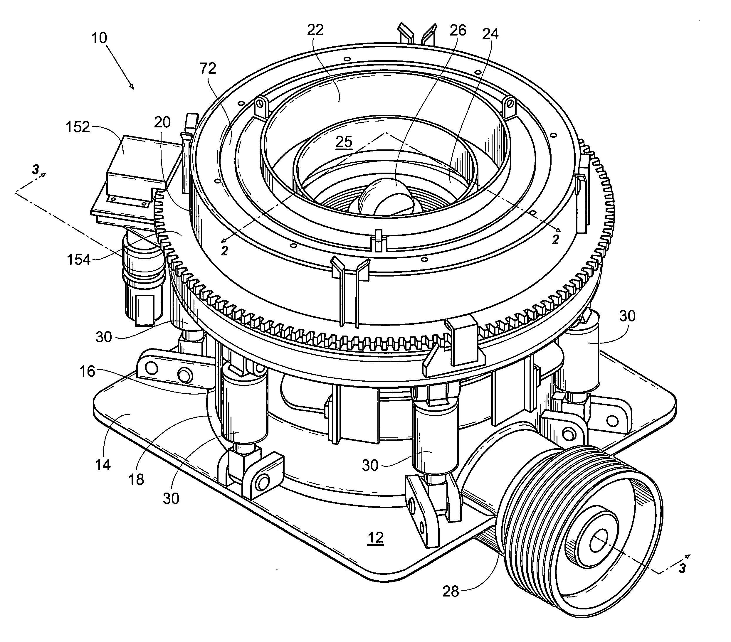
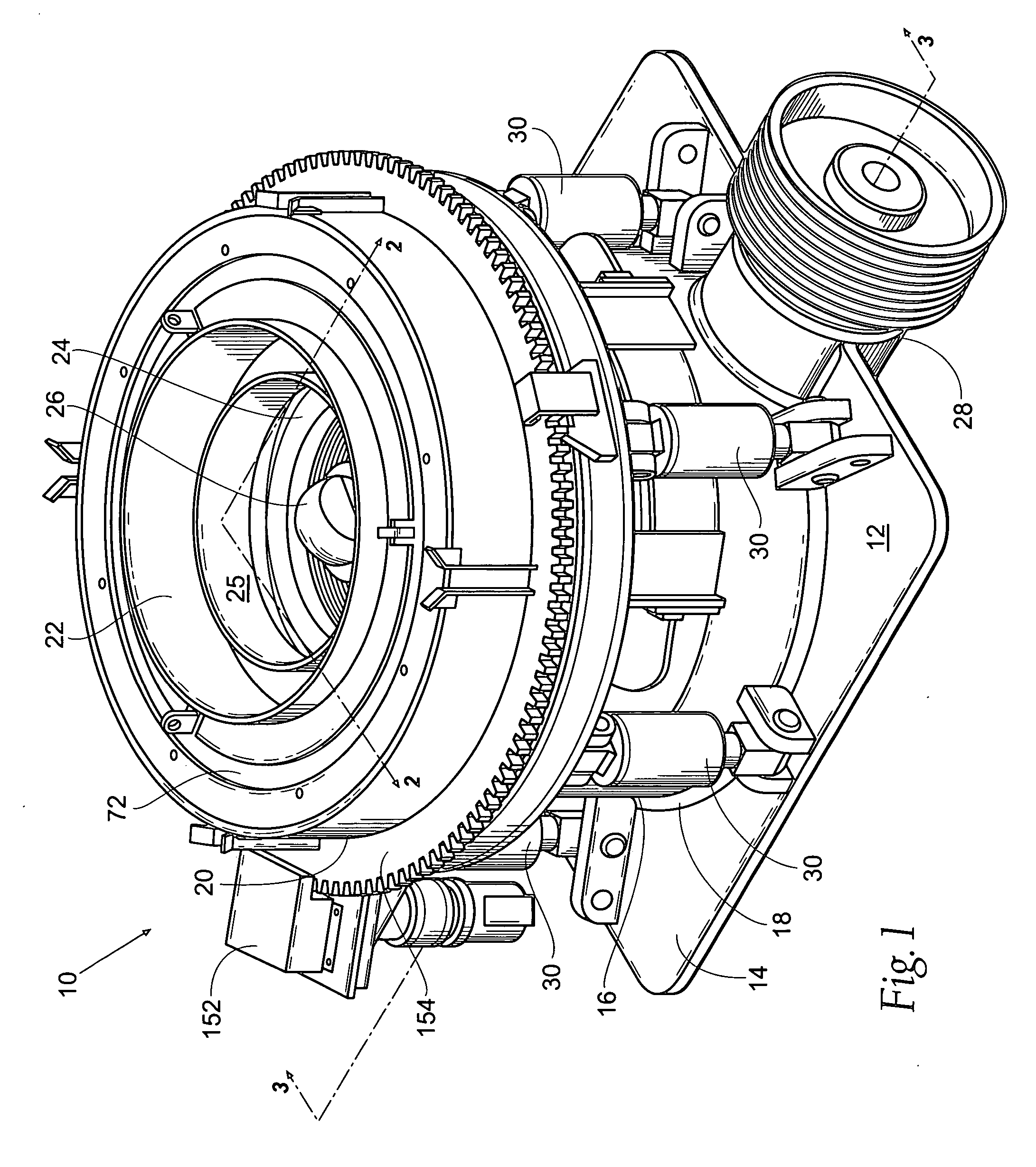
[0024]FIG. 1 shows a perspective view of a rock crusher 10 according to the present invention. The rock crusher 10 comprises a mainframe 12, comprising a base 14 and a body 16. The body 16 has a first end 18 connected to the base 14 and a second end 20 that supports an adjustment ring 72. A crusher bowl 24 is assembled into the adjustment ring 72 and is vertically adjustable through its rotation in relationship to the adjustment ring 72. The crusher bowl 24, along with a head and shaft assembly 26 that further comprises a crusher head 43 (see FIG. 3), forms a crushing cavity 25 for rock crushing...


PUM


Abstract

An improved cone-style rock crusher. The rock crusher may be adjusted for varying rock crushing specifications, including different speeds, throws, and liners. The rock crusher comprises a frame that supports a crushing bowl, a crusher head and a shaft, with the shaft being secured to the crusher head. A domed feed plate may be secured onto the crusher head for assistance in secondary rock crushing processes. An eccentric bushing allows the shaft to be aligned properly, regardless of whether there is a load or not within the crushing bowl. The bushing is tapered downwardly, which allows for evenly dispersed contact along the length of the shaft as it gyrates. Furthermore, the thickness of the bushing is asymmetrical. The rock crusher further comprises uniquely designed tramp release cylinders that provide a safeguard that acts as shock absorbers when the rock crusher encounters tramp material.

Description

RELATED APPLICATIONS [0001] This application is a continuation-in-part of patent application Ser. No. 10 / 861,953, filed on 4 Jun. 2004.BACKGROUND OF THE INVENTION [0002] The present invention relates to rock crushers and improved cone-style rock crushers that provide optimal performance for each rock crushing application. [0003] Numerous rock crushers have been designed to crush and fragment rocks into smaller pieces. Cone-style crushers are a common type of rock crushers. Rocks are fed into the crusher through a rotating feed distributor or on top of the feed plate, which distributes the rocks into a crushing cavity. A crusher head mounted on a shaft is located within the crushing bowl. The shaft rotates or gyrates and crushes the entering rocks. The rocks exit below the crusher and are carried away for further sorting, or to be recycled and reprocessed in the rock crusher. [0004] However, due to the demanding environment that rock crushers are employed within, repair and maintenan...

Claims


Application Information

Patent Timeline
Patent Type & Authority Applications(United States)
IPC IPC(8): B02C2/00B02C2/02B02C2/04
CPCB02C2/04
Inventor SAWANT, ULHAS S.SHERIDAN, JAMES A.
Owner INNOTECH SOLUTIONS
Why Eureka
Try Eureka