Distributed printing control device and print job distribution method

a technology of printing control device and printing job, which is applied in the direction of digital output to print unit, instruments, digital computers, etc., to achieve the effect of simple system configuration and reduced mixing

Inactive Publication Date: 2005-12-08
SEIKO EPSON CORP
View PDF9 Cites 33 Cited by
  • Summary
  • Abstract
  • Description
  • Claims
  • Application Information

AI Technical Summary

Benefits of technology

[0007] The object of the invention is thus to eliminate the drawbacks of the prior art technique and to implement distributed printing with the mixing reduced by a simple system configuration.

Problems solved by technology

Additionally, mixing of printed matter due to the distributed printing causes a problem.

Method used


Image

  • Distributed printing control device and print job distribution method
  • Distributed printing control device and print job distribution method
  • Distributed printing control device and print job distribution method

Examples


first embodiment

A. First Embodiment

A1. System Configuration

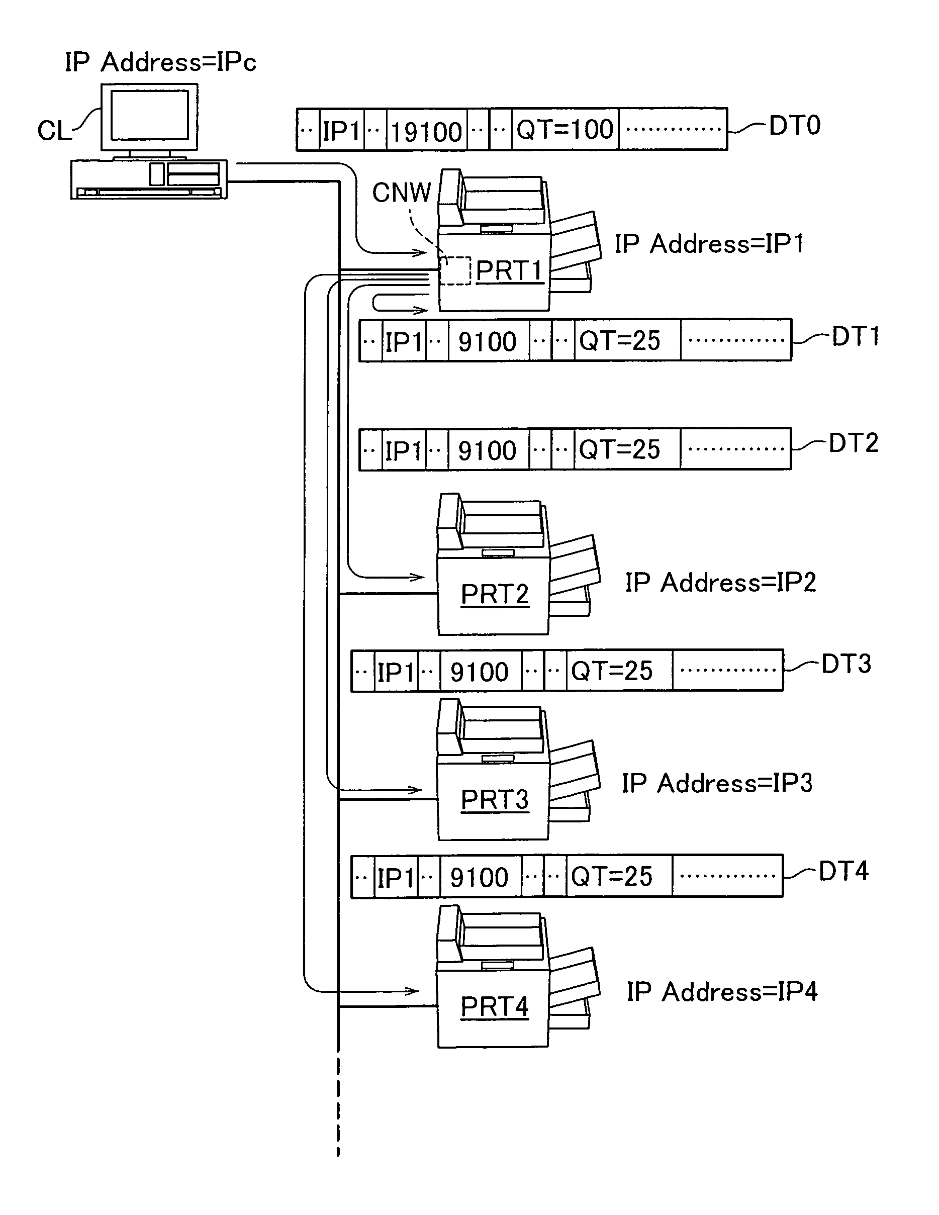
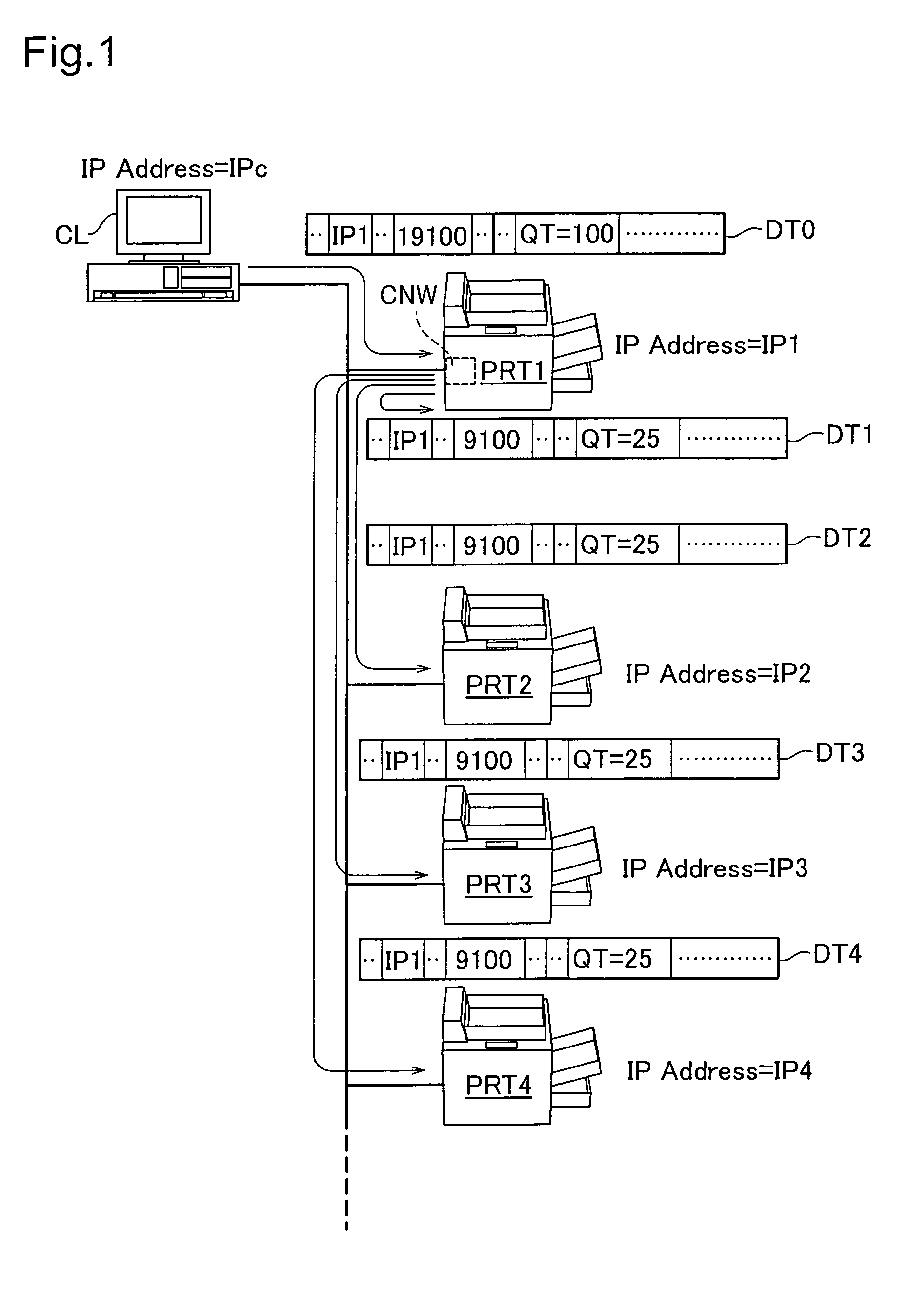
[0065]FIG. 1 schematically illustrates the configuration of a printing system including a printer PRT1 in a first embodiment of the invention. As illustrated, in this printing system, a client PC (hereafter referred to as the client) CL and multiple printers PRT1 through PRT4 are connected to a local area network (LAN). Communication between the respective devices is on the basis of the TCP / IP protocol, and fixed IP addresses are allocated to the respective devices. For convenience of explanation, it is here assumed that an IP address ‘IPc’ is allocated to the client CL and that IP addresses ‘IP1’ to ‘IP4’ are respectively allocated to the printers PRT1 to PRT4. Strictly speaking, these IP addresses are not set in the client CL and the printers PRT1 to PRT4, but are set at nodes in the TCP / IP network (for example, network boards connected to the network for TCP / IP communication).

[0066] A custom network board CNB is mounted on the printer...

second embodiment

B. Second Embodiment

[0148] The technique of the first embodiment uses the identical non-procedural printing protocol but different port numbers, that is, the general number ‘9100’ and the particular number ‘19100’, in the process of sending the print job from the client CL to the printer PRT1 having the distributed printing control functions and in the process of sending the print job from the printer PRT1 to the specified distribution destination printers to achieve distributed printing. The technique of a second embodiment uses different printing protocols in the process of sending the print job from the client CL to the printer PRT1 having the distributed printing control functions and in the process of sending the print job from the printer PRT1 to the specified distribution destination printers to achieve distributed printing.

[0149] B1. Structure of Printer

[0150]FIG. 8 mainly shows the structure of the printer PRT1 in the second embodiment of the invention. The structure of t...

third embodiment

C3. Third Embodiment

[0170] In the first and the second embodiments discussed above, the copy number setting module 24 sets the distributed copy numbers to be distributed to the respective distribution destination printers as equally as possible. In a printing system of a third embodiment, the copy number setting module 24 inquires about the remaining quantity of toner to the respective distribution destination printers and sets the distributed copy numbers to be distributed to the respective distribution destination printers by referring to the responses on the remaining quantity of toner.

[0171] The structures of the printers and the general printing process in the third embodiment are substantially identical with those of the first or the second embodiment and are thus not specifically described here.

[0172] C1. Distributed Printing Process

[0173] A distributed printing process executed in the third embodiment is described. Only the partial flow of the distributed printing process...


PUM


Abstract

This invention provides a distributed printing method. This method distributes a print job sent via a network to at least one distribution destination printing device specified as a distribution destination among printing devices connected to the network. The method includes the steps of: (a) providing a print job storage unit; (b) receiving communication data including the print job; (c) storing the print job included in the communication data into the print job storage unit; (d) determining if the storage is completed; (e) determining the distribution destination printing device from among the printing device connected to the network, in response to the determination of completion; (f) distributing the print job stored in the print job storage unit to the distribution destination printing device so as to have one copy each printed at each of the distribution destination printing devices; and (g) controlling each of the distribution destination printing device so that printed matter other than the printed matter generated by the print job is not mixed with the printed matter generated by the print job for each of the distribution destination printing device.

Description

CROSS-REFERENCE TO RELATED APPLICATIONS [0001] This application is a continuation-in-part of application Ser. No. 10 / 996,840, filed Nov. 24, 2004, the disclosure of which is incorporated herein by reference. This application also claims priority under 35 U.S.C. § 119 from Japanese Patent Application No. 2004-140093, filed May 10, 2004.BACKGROUND OF THE INVENTION [0002] 1. Field of the Invention [0003] The present invention relates to a technique of distributing a print job to at least one printing device connecting with a network and thereby attaining distributed printing. [0004] 2. Description of the Related Art [0005] A printing system including multiple printers connected to an identical network has widely been used to enable each user to selectively use the multiple printers. A distributed printing technique has also been proposed to distribute a print job of printing multiple copies to plural printers for parallel printing and thereby complete printing in a short time period (s...

Claims


Application Information

Patent Timeline
Patent Type & Authority Applications(United States)
IPC IPC(8): B41J29/38G06F3/12G06F15/00
CPCH04N1/00915H04N1/32502H04N1/32523H04N1/32555H04N1/32609H04N1/32635H04N1/32678H04N1/327H04N1/32795
Inventor SHIMA, TOSHIHIROTANIGUCHI, SHINYA
Owner SEIKO EPSON CORP
Why Eureka
Try Eureka