Charging apparatus, and image forming apparatus equipped with same

a charging apparatus and image forming technology, applied in the direction of electrographic process apparatus, corona discharge, instruments, etc., can solve the problems of reducing charging performance, affecting the charging current, and fouling the surface of the photosensitive body, so as to prevent the effect of filming and filming defects, suppressing charging current fluctuations, and preventing filming defects

Inactive Publication Date: 2005-12-08
RICOH KK
View PDF13 Cites 30 Cited by
  • Summary
  • Abstract
  • Description
  • Claims
  • Application Information

AI Technical Summary

Benefits of technology

[0016] It is a first object of the present invention to provide a charging apparatus, process cartridge, and image forming apparatus with which fluctuations in the charging current can be suppressed, and image defects caused by filming and the like can be prevented, by specifying a permissible gap fluctuation value by quantitatively ascertaining the relationship between the fluctuation in charging current and the fluctuation in the gap between the photosensitive body and the charging roller.

Problems solved by technology

Nevertheless, because the charging roller used in such charging apparatus involving contact charging is produced by providing an elastic roller component molded from an electroconductive rubber over the outside of a metal core, for example, when this elastic roller component is left pressed against the surface of the photosensitive body for an extended period, the substances contained in the elastic roller component, such as a plasticizer, can ooze out onto the surface, where they can foul the surface of the photosensitive body.
Also, with this contact charging apparatus, since the charging is performed with the charging roller or other charging member in contact with the surface of the photosensitive body, any untransferred toner or the like remaining on the surface of the photosensitive body after image transfer ends up moving to and fouling the surface of the charging member, and this is sometimes a cause of diminished charging performance.
Unfortunately, with a non-contact charging apparatus in which the photosensitive body and the charging roller are brought close together but without touching, the gap between the photosensitive body and the charging roller can change over time, resulting in a change in the charging current, which leads to image inconsistency and other such problems.
A problem with this proposal, however, was that the fluctuation in charging current brought about by a change in the gap between the photosensitive body and the charging roller over time was not taken into account, so the amount of current and other such conditions related to the occurrence of filming and so forth could not be factored in, and the permissible range for gap fluctuations had to be determined empirically.
Meanwhile, with the above-mentioned electrophotographic image forming apparatus, the parts characteristic of an electrophotographic process, consisting of an photosensitive body, a charging apparatus, a developing apparatus, and so on, are prone to mechanical wear and toner fouling.
However, a problem is that when the charging roller and the power supply of the charging apparatus are far apart, stray capacity generates current in the power cable, and the original AC current and the current flowing into the stray capacity cannot be accurately detected, depending on the position of the means for detecting AC current produced by feedback current.
Since this stray capacity varies with the environment, the harness cable routing, and so forth, it is difficult to estimate the inflow current that will be generated by stray capacity, so a problem is that filming cannot be prevented by quantitatively detecting the AC current.

Method used


Image

  • Charging apparatus, and image forming apparatus equipped with same
  • Charging apparatus, and image forming apparatus equipped with same
  • Charging apparatus, and image forming apparatus equipped with same

Examples


first embodiment

[0039] This embodiment is primarily intended to achieve the above-mentioned first object of the present invention.

[0040] This embodiment will now be described in detail through reference to the drawings.

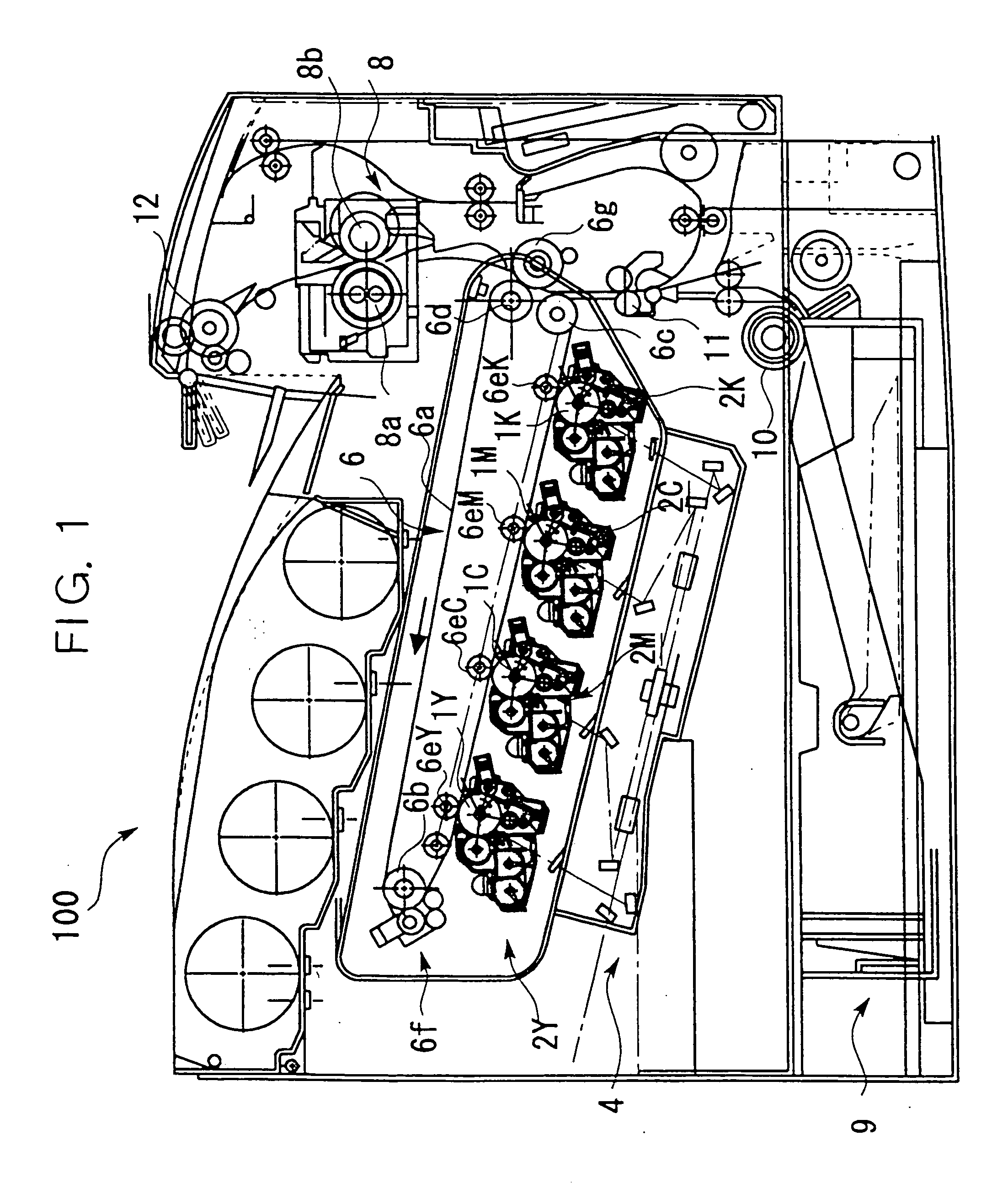
[0041]FIG. 1 illustrates the constitution of an image forming apparatus 100 pertaining to this embodiment. The description here will be for an example applied to the electrophotographic image forming apparatus 100.

[0042] This image forming apparatus 100 forms a color image from four colors of toner: yellow (hereinafter referred to as “Y”), cyan (hereinafter referred to as “C”), magenta (hereinafter referred to as “M”), and black (hereinafter referred to as “K”). The image forming apparatus 100 comprises four photosensitive bodies 1Y, 1C, 1M, and 1K serving as latent image carriers. The photosensitive bodies 1Y, 1C, 1M, and 1K are each rotated in the direction of the arrow in the drawing while in contact with an intermediate transfer belt 6a (surface movement member).
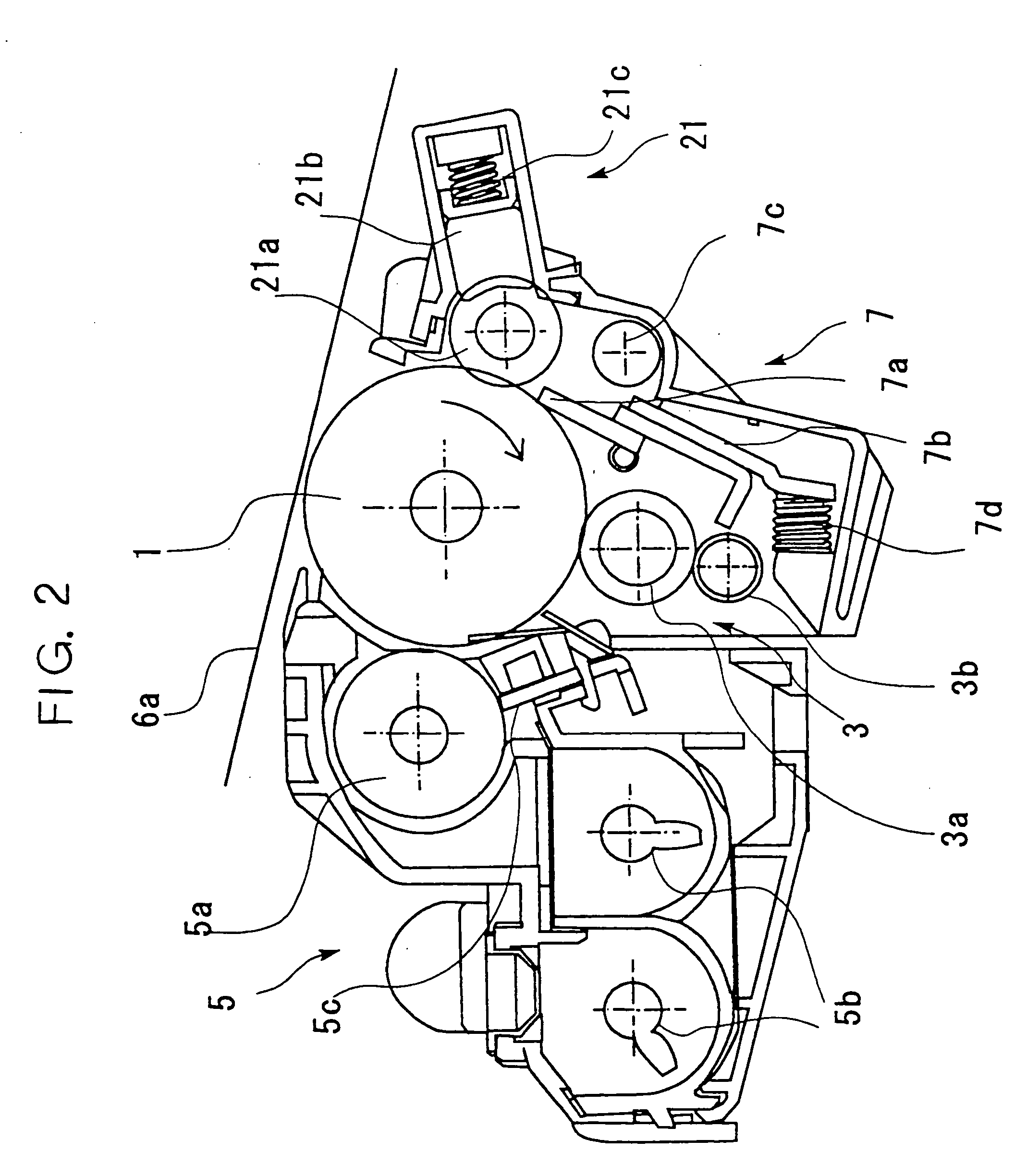
[0043]FIG. 2 ...

second embodiment

[0137] This embodiment is primarily intended to achieve the above-mentioned second object of the present invention.

[0138]FIGS. 1, 2, 3, 9A, 9B, and 10A to 10C referred to in the first embodiment above, and the descriptions of these drawings, all substantially apply to this embodiment as well, so these drawings will not be described again.

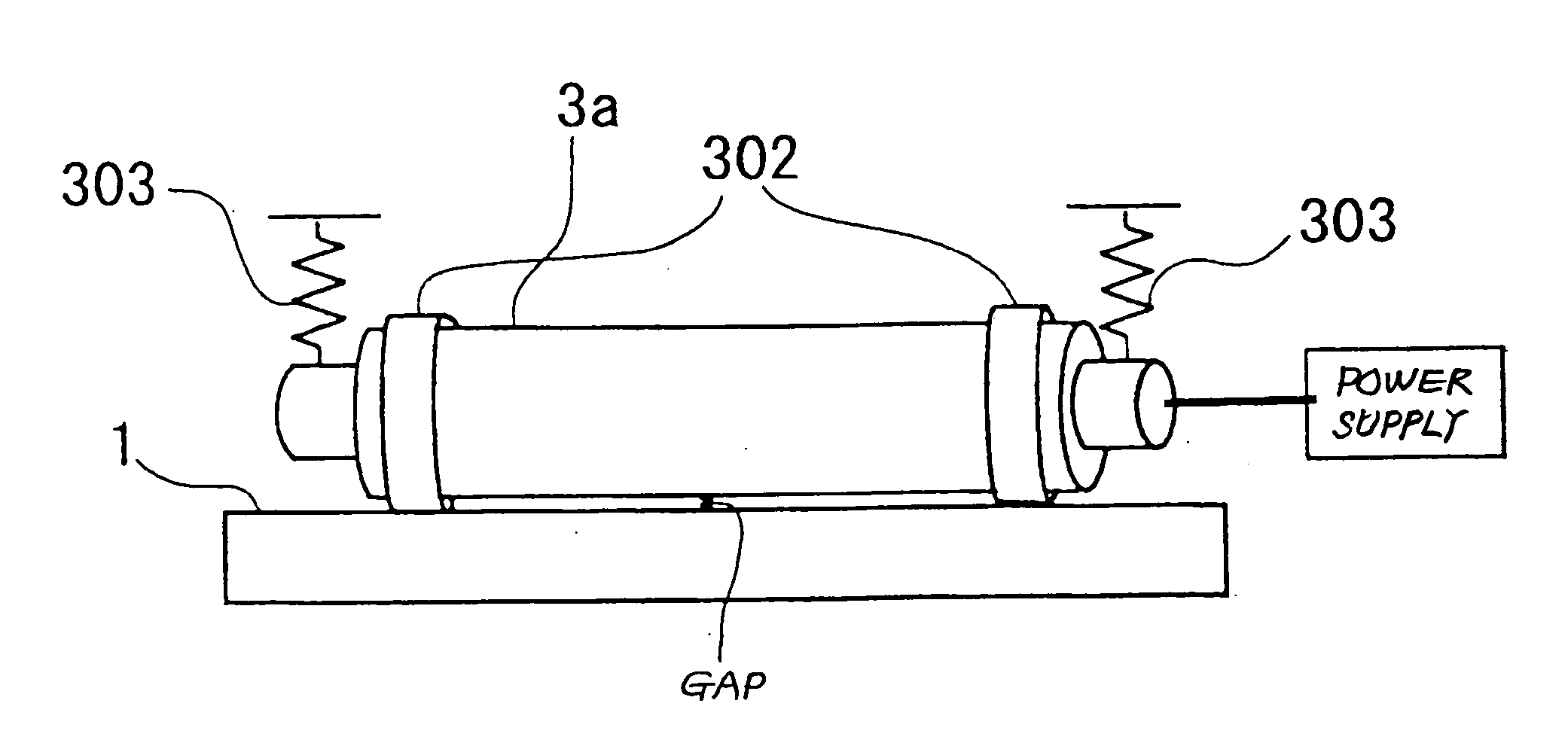
[0139] As discussed above, again in this embodiment, the charging roller 3a is connected to a power supply, and a specific voltage is applied thereto. This voltage consists of alternating current (AC) voltage superimposed over DC voltage. Applying AC voltage allows the surface of the photosensitive drum 1 to be charged more uniformly. As discussed above, however, if too much AC current flows, filming will occur on the photosensitive body surface, so the AC current level needs to be precisely controlled.

[0140]FIG. 11 illustrates the constitution of a power supply circuit and an AC current detection means of the charging apparatus pertaining to thi...


PUM


Abstract

A charging apparatus, process cartridge, and image forming apparatus with which current fluctuation values in the charging current can be suppressed, and image defects caused by filming and the like can be prevented, by specifying a permissible gap fluctuation value by quantitatively ascertaining the relationship between the fluctuation value in charging current and the fluctuation value in the gap between the photosensitive body and the charging roller. In a charging apparatus equipped with a charging roller provided at a minute gap away from a photosensitive body, for performing charging, the relationship Gmax−Gmin≦30 (μm) is satisfied when the gap (μm) between the charged side of the photosensitive body and the charging side of the charging roller has a maximum value Gmax (μm) and a minimum value Gmin (μm).

Description

BACKGROUND OF THE INVENTION [0001] 1. Field of the Invention [0002] The present invention relates to an image forming apparatus that makes use of an electrophotographic process, such as a copier, printer, or fax machine, and more particularly relates to an image forming apparatus equipped with a non-contact type of charging apparatus that performs charging by superimposing an AC bias voltage over a DC bias voltage as the charging bias voltage. [0003] 2. Description of the Related Art [0004] With an electrophotographic image forming apparatus, a charging treatment is performed by imparting a charge of a specific polarity, produced by discharge, to the surface of a photosensitive body (image carrier), the surface of the photosensitive body is exposed to light to form an electrostatic latent image, and toner that has been charged to the same polarity as this electrostatic latent image is supplied from a developing apparatus, thereby forming a toner image. The toner image formed on the ...

Claims


Application Information

Patent Timeline
Patent Type & Authority Applications(United States)
IPC IPC(8): G03G15/02
CPCG03G15/0266
Inventor ARAI, YUJIOJIMI, TOKUYATAWADA, TAKAAKIKOIKE, TOSHIOAMEMIYA, KENSHINTANI, TAKESHIKAWASUMI, MASANORIYONEDA, TAKUZITOMITA, MASAMIUCHITANI, TAKESHIKUWABARA, NOBUONAGASHIMA, HIROYUKIONO, HIROSHIFUJISHIRO, TAKATSUGUMIZUISHI, HARUJIYOKONO, MASAHARU
Owner RICOH KK
Why Eureka
Try Eureka