Pump device

a pump body and fluid technology, applied in the direction of positive displacement liquid engines, pump bodies, machines/engines, etc., can solve the problems of difficult operation of only one pump body, difficult downsizing, etc., and achieve the effect of easy miniaturization and small flow ra

Inactive Publication Date: 2005-12-08
SANKYO SEIKI MFG CO LTD
View PDF7 Cites 10 Cited by
  • Summary
  • Abstract
  • Description
  • Claims
  • Application Information

AI Technical Summary

Benefits of technology

[0007] In view of the problems described above, the present invention may advantageously provide a pump device that can be easily miniaturized and can obtain a little flow rate.

Problems solved by technology

However, in the above-mentioned circulating pump 100, the diaphragms 101 are disposed on the same plane and thus downsizing is difficult while maintaining the size of the pump body 102.
Therefore, it is difficult to operate only one of the pump bodies 102 at a time in order to obtain a little flow rate.

Method used


Image

  • Pump device
  • Pump device
  • Pump device

Examples


Embodiment Construction

[0047] Several embodiments of the present invention will be described in detail below with reference to the accompanying drawings.

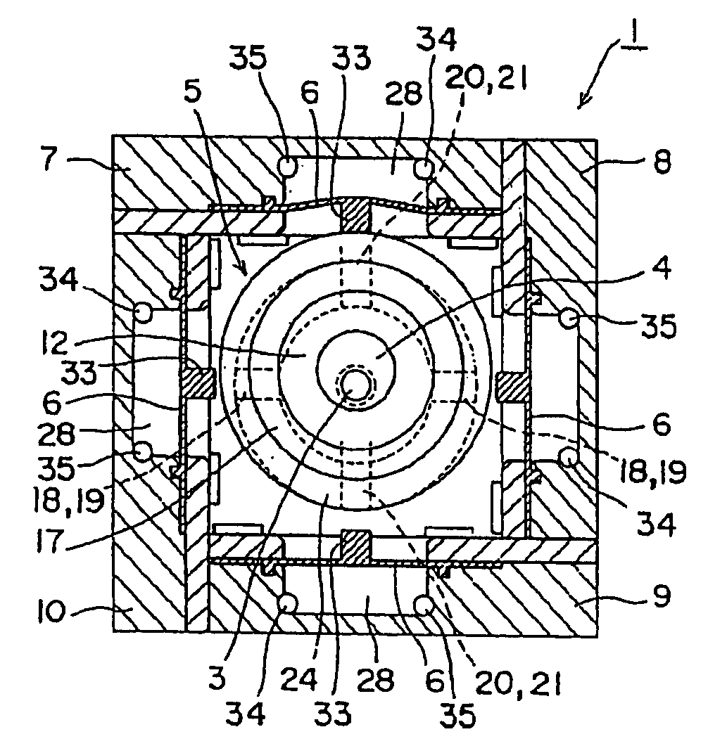
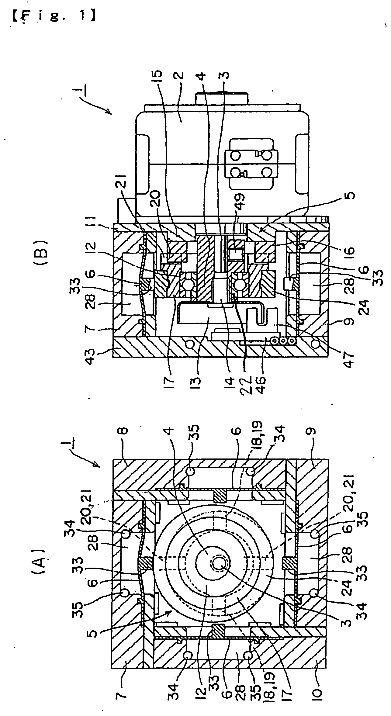
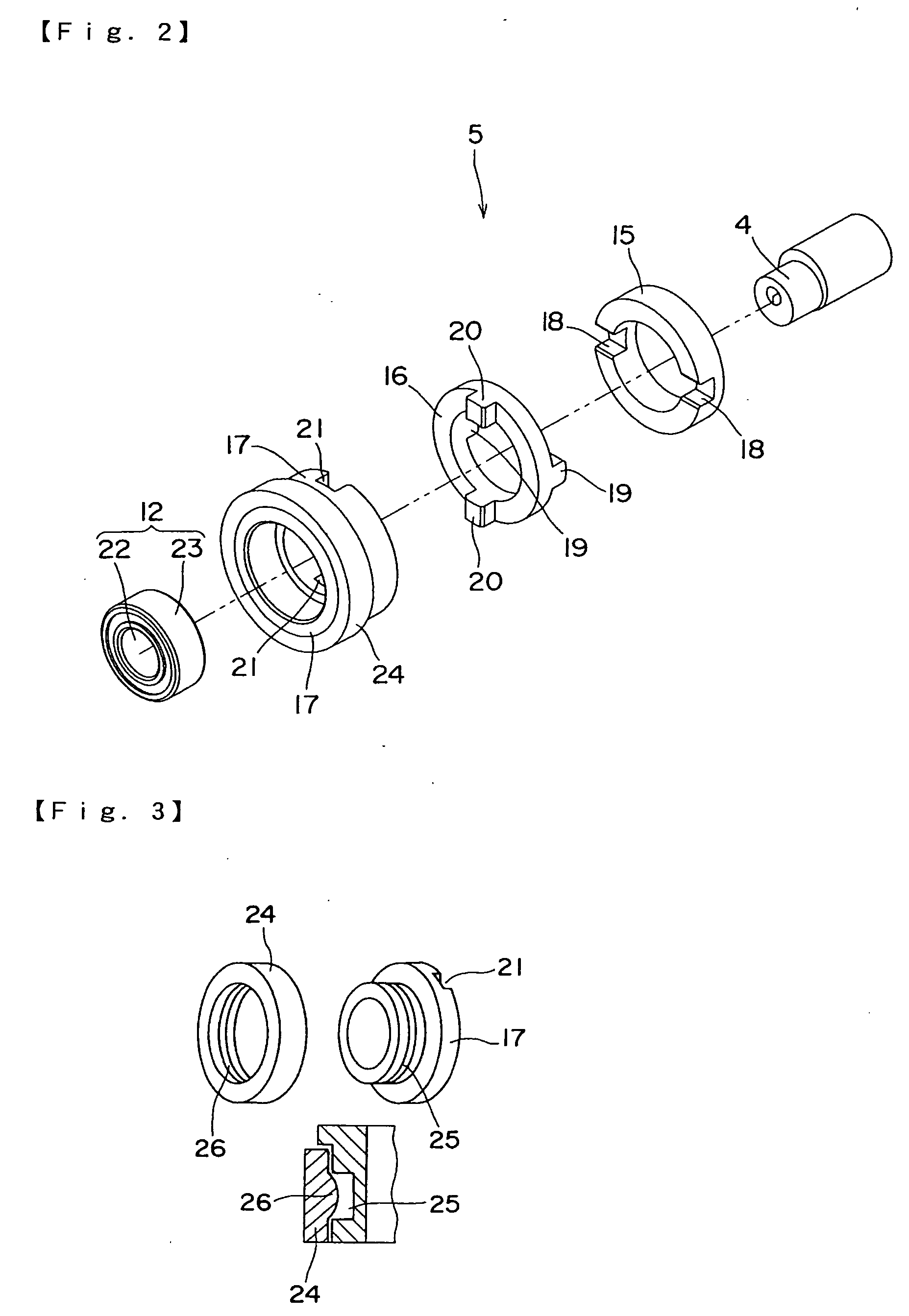
[0048] A pump device 1 in accordance with an embodiment of the present invention is shown in FIGS. 1 through 15. The pump device 1 includes a motor 2, an eccentric member 4 eccentrically mounted on the output shaft 3 of the motor 2, a cam mechanism 5 which engages with the eccentric member 4 for converting the turning or rotating motion of the eccentric member 4 into a motion in a radial direction of the output shaft 3, and pump bodies 7 through 10 each of which is provided with a diaphragm 6 for performing a pump operation that is moved in the radial direction of the output shaft 3 by the operation of the cam mechanism 5 as shown in FIGS. 1(A) and 1(B).

[0049] The motor 2 is a stepping motor. The motor 2 is mounted on a support plate 11 with a screw. The inner ring 22 of a ball bearing 12 is mounted on the eccentric member 4, for example, by press fitti...


PUM


Abstract

A pump device may include an eccentric member mounted on an output shaft in an eccentric manner, a cam mechanism which is engaged with the eccentric member to convert a motion of the output shaft into a radial direction and at least one pump body which includes a diaphragm that is moved in the radial direction in relation to the output shaft by the cam mechanism for performing a pumping operation.

Description

CROSS REFERENCE TO RELATED APPLICATION [0001] The present invention claims priority under 35 U.S.C. § 119 to Japanese Application No. 2004-166205 filed Jun. 3, 2004, which is incorporated herein by reference. FIELD OF THE INVENTION [0002] The present invention relates to a pump device for circulating fluid. More specifically, the present invention relates to a pump device provided with a pump body utilizing a diaphragm. BACKGROUND OF THE INVENTION [0003] A conventional circulating pump 100 has been known in which a plurality of pump bodies 102 are provided for sucking and compressing fluid by means of the operation of diaphragms 101 and the diaphragms 101 of the respective pump bodies 102 are disposed on the same plane as shown in FIG. 26 (see Japanese Patent Laid-Open No. Hei 11-62837). The circulating pump 100 includes a motor 103 as a drive source, a rotation shaft 104 rotated by the motor 103 and provided with an end face slightly inclined with respect to its rotation center, a ...

Claims


Application Information

Patent Timeline
Patent Type & Authority Applications(United States)
IPC IPC(8): F04B43/02F04B17/00F04B35/04F04B43/00
CPCF04B43/0054
Inventor MURAMATSU, KENJIIIZAWA, MOTOHIRO
Owner SANKYO SEIKI MFG CO LTD
Why Eureka
Try Eureka