Method for producing a moulded article comprising a sprayed polyurethane layer

a polyurethane layer and moulding technology, applied in the direction of superimposed coating process, liquid/solution decomposition chemical coating, manufacturing tools, etc., can solve the problem of clogging or no longer being made in practice, reaction mixture receiving too much kinetic energy, and/or too small droplets

Active Publication Date: 2012-11-27
RECTICEL AUTOMOBIL SYSTEME GMBH
View PDF16 Cites 8 Cited by
  • Summary
  • Abstract
  • Description
  • Claims
  • Application Information

AI Technical Summary

Benefits of technology

[0006]The solution offered by the present invention to solve this problem consists in that the flow of reaction mixture achieves in the channel or channels wherein the reaction mixture is accelerated a total minimum cross-sectional area of S mm2, with S being a value smaller than 1.0, and preferably smaller than 0.9, in that the reaction mixture is sprayed out of the nozzle at a flow rate of between 10×S and 80×S g / sec, and in that, per gram reaction mixture, an amount of 0.05 to 2.5 mmol of a pressurised gas is sprayed together with the reaction mixture through said spray opening out of the nozzle to increase the kinetic energy of the reaction mixture which is sprayed out of the nozzle.
[0007]Due to the relatively small cross-sectional area of the channel or channels wherein the reaction mixture is accelerated, the reaction mixture can be sprayed at a relatively small flow rate. This flow rate can further be reduced by the addition of the gas to the reaction mixture before the reaction mixture is sprayed out of the nozzle since the addition of pressurised gas increases the kinetic energy of the reaction mixture and thus enables to achieve a stable spray pattern with a smaller flow rate of the reaction mixture. Compared to the existing air atomisation nozzles or air-assisted atomisation nozzles, the pressurised gas is added in accordance with the present invention only in relatively small amounts so that the reaction mixture droplets do not receive too much kinetic energy and the layer of reaction mixture sprayed on the mould surface is not disturbed, or at least not too much, by the flow of gas and reaction mixture sprayed out of the nozzle. Such low amounts of gas are possible due to the fact that the reaction mixture is sprayed at a flow rate higher than a minimum flow rate through the channel or channels wherein it is accelerated.

Problems solved by technology

Indeed, when spraying higher amounts of reaction mixture per surface area and per time unit, the desired low flow rate cannot be obtained without reducing the size of said channel or channels to such an extent that they will either clog or that they can no longer be made in practice.
When spraying, on the other hand, smaller amounts of reaction mixture, too much gas is required to form a stable spray pattern so that the reaction mixture receives too much kinetic energy and / or is atomised in too small droplets.
Even when having applied first a so-called in-mold coating as finishing layer onto the mould surface, problems arise when the reaction mixture has to be sprayed from a short spray distance.
Indeed, due to the high amount of kinetic energy, the reaction mixture which is sprayed on the mould surface will be blown aside by the force of the reaction mixture which is being sprayed on the mould surface so that it is not possible to obtain a uniform thickness.
The in-mold coating may even be damaged by the impact of the reaction mixture especially when using a flat instead of a three-dimensional spray pattern.

Method used


Image

  • Method for producing a moulded article comprising a sprayed polyurethane layer
  • Method for producing a moulded article comprising a sprayed polyurethane layer
  • Method for producing a moulded article comprising a sprayed polyurethane layer

Examples


example

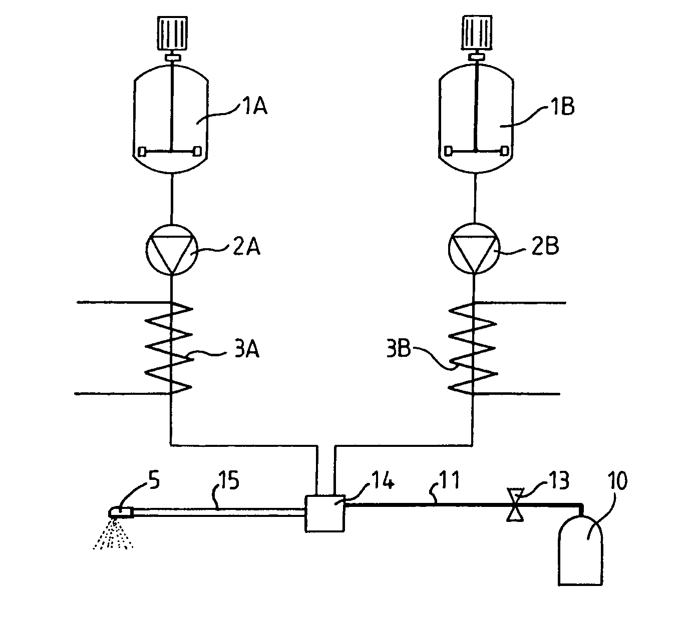
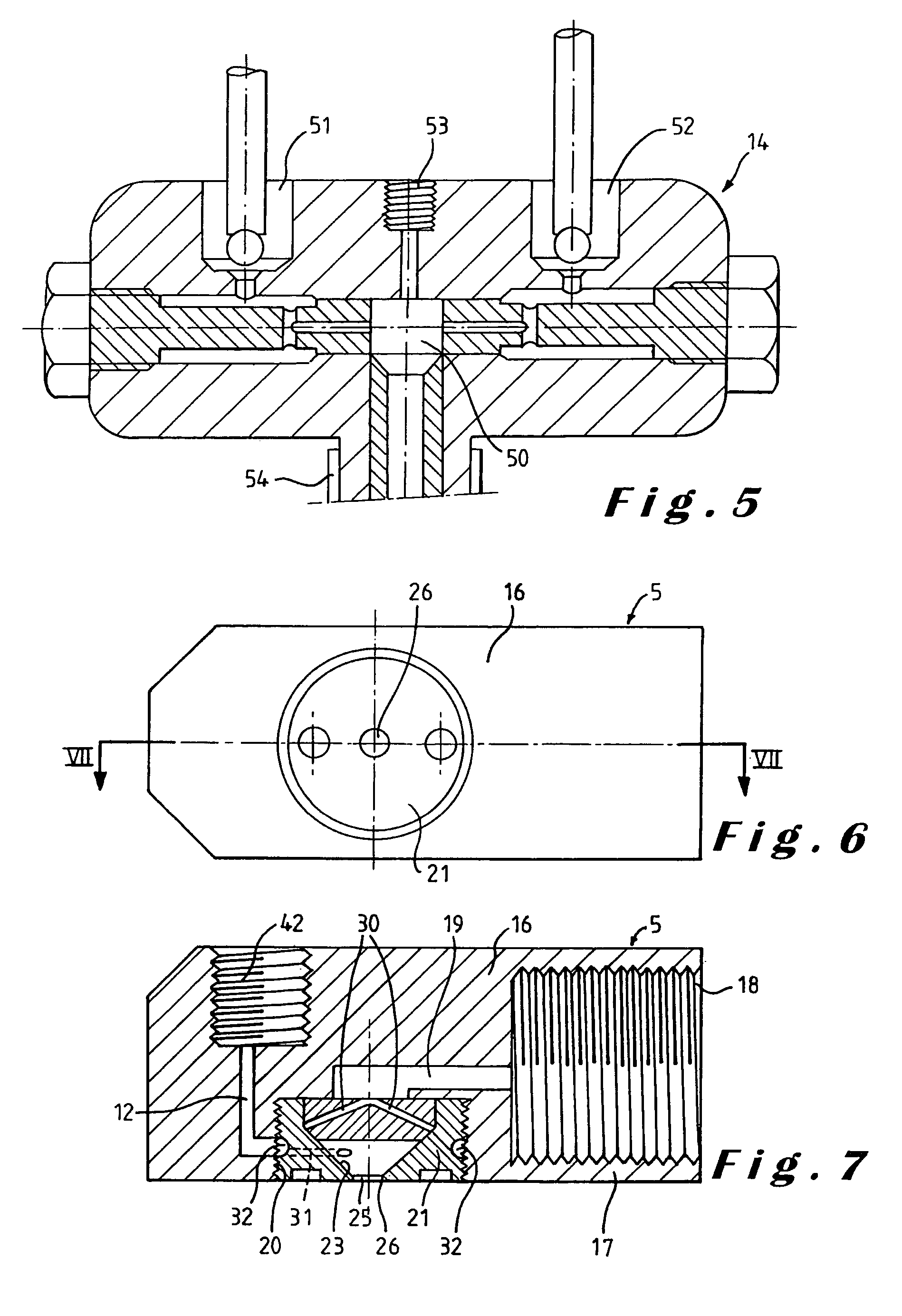
[0072]By means of a spray nozzle wherein pressurised nitrogen gas was mixed in the same way into a polyurethane reaction mixture as illustrated in FIG. 10 a flexible elastomeric polyurethane layer was sprayed in a thickness of 0.7 mm on a mould surface. The supply channel 19 of the reaction mixture had a diameter of about 1 mm whilst the total minimum cross-sectional area of the four grooves 29, measured at their downstream end, was about 0.35 mm2.

[0073]When spraying the reaction mixture at about 8 g / sec and injecting the nitrogen gas at a flow rate of about 4 g N2 / min, a stable spray pattern was obtained and the sprayed polyurethane layer had a density of about 950 g / l.

[0074]When using a similar prior art nozzle, having no possibility to supply a gas, the same stable spray pattern could be achieved but only with a flow rate of the reaction mixture of about 14 g / sec. This shows that a very limited addition of pressurised gas enables a substantial reduction of the flow rate of the re...


PUM

PropertyMeasurementUnit
total cross-section areaaaaaaaaaaa
volume diameteraaaaaaaaaa

Abstract

For producing a polyurethane layer by spraying a polyurethane reaction mixture, this mixture is supplied under pressure to a spray nozzle, within the nozzle the reaction mixture is accelerated by passing it through one or more channels having a reduced cross-sectional area, and the accelerated reaction mixture is sprayed, with a predetermined amount of kinetic energy, through a spray opening out of the spray nozzle onto a surface. The channels wherein the reaction mixture is accelerated have a total minimum cross-sectional area of S mm2, S being a value smaller than 1.0, the reaction mixture is sprayed out of the nozzle at a flow rate of between 10×S and 80×S g / sec, and, per gram reaction mixture, an amount of 0.05 to 2.5 mmol of a pressurized gas is sprayed together with the reaction mixture through said spray opening out of the nozzle to increase the kinetic energy of the reaction mixture which is sprayed out of the nozzle. By the addition of a pressurized gas to the reaction mixture, a same or even a better spray pattern can be achieved and the reaction mixture can be sprayed at a smaller flow rate.

Description

[0001]This is a Continuation-in-Part of International Application No. PCT / EP2004 / 051211, filed Jun. 23, 2004, the entire disclosure of which is hereby incorporated by reference.BACKGROUND OF THE INVENTION[0002]The present invention relates to a method for producing an article comprising at least a polyurethane layer, in which method a polyurethane reaction mixture is supplied under pressure to a spray nozzle, within the nozzle the reaction mixture is accelerated by passing it through one or more channels wherein the flow of reaction mixture achieves a minimum cross-sectional area measured perpendicular to the flow of the reaction mixture, the accelerated reaction mixture is sprayed, with a predetermined amount of kinetic energy, through a spray opening out of the spray nozzle onto a surface to produce said polyurethane layer and the reaction mixture is allowed to cure.[0003]Such a method is disclosed in EP-B-0 303 305 and in EP-B-0 389 014. In the known method an elastomeric polyure...

Claims


Application Information

Patent Timeline
Patent Type & Authority Patents(United States)
IPC IPC(8): B05D1/02B05B1/34B05B7/04B05B7/10B05B7/26B05D1/34
CPCB05B1/3442B05B7/0408B05B7/0416B05B7/10B29C41/08B05B7/267B05D1/02B05D1/34B29K2075/00B29L2031/3005
Inventor DE WINTER, HUGOSTALPAERT, GERTWILLEMS, JAN
Owner RECTICEL AUTOMOBIL SYSTEME GMBH
Why Eureka
Try Eureka