
Process for producing a flat panel radiation detector and a flat panel radiation detector

a flat panel radiation detector and flat panel technology, applied in the field of flat panel radiation detectors, can solve the problems of deformation or damage of the upper plate, the expansion of the center of the upper plate upward, and the conventional art with such a composition has the following problems

Inactive Publication Date: 2005-12-08
SHIMADZU CORP
View PDF2 Cites 0 Cited by
  • Summary
  • Abstract
  • Description
  • Claims
  • Application Information

AI Technical Summary

Benefits of technology

[0009] The object of the present invention is to overcome the problems described above and to provide a process for producing a flat panel radiation detector and a flat panel radiation detector, wherein damage to the flat panel radiation detector caused by a resin may be prevented by injecting a large amount than the predetermined amount of the resin.
[0012] Because the restricting member is disposed by way of the spacer in the present invention according to claim 1, the upper plate is allowed to expand upward on injection of the resin, but unnecessary overexpansion is restricted by the restricting member. The high pressure applied to the resin in the space by the upper plate expanding upward makes the whole resin contract evenly in the space on curing of the resin. At this time the restoring force is applied to the upper plate. Since the restoration is taking place from the expanded state to the original state, no excess force is applied. Rather, it mitigates the stress in the expanded state, preventing damaging force to the upper plate. Thus even if a large amount resin than necessary is injected, the upper palate is not deformed severely or damaged, and therefore a large amount resin than the predetermined amount can be injected. As a result damage to the upper plate caused by the injection of the resin, and damage to the upper plate and the exfoliation of the radiation sensitive layer and the like caused by the curing of the resin may be prevented, and the damage to the flat panel radiation detector may be prevented.
[0013] Further, in the present invention, it is preferable that the spacer and the restricting member are composed as one unit and a recess is formed at the lower face of the restricting unit fitting to the expanded shape of the upper plate (claim 2). A stable expansion of the upper plate is allowed by forming the recess fitting to the expanded shape of the upper plate because the center of the upper plate expands upward most. Therefore, always a large amount resin than the predetermined amount may be injected. Moreover, since the spacer and the restricting member are composed as one unit, the installation to the flat panel radiation detector is easy.
[0015] Furthermore, in the present invention it is preferable that the flat panel radiation detector is produced by any one of the process for producing a flat panel radiation detector according to claims 1-4 (claim 5). Since the damage to the upper plate and the exfoliation of the radiation sensitive layer may be prevented, the reliability of the radiation detector may be improved.
[0016] (Operation and Advantage) With the implementation of the process for producing the flat panel radiation detector in the present invention, the upper plate is not deformed severely or damaged when a large amount of resin is injected because the restricting member is disposed by way of the spacer and furthermore a large amount of resin may be injected than the predetermined amount. Thus the damage to the upper plate caused by the injection of the resin, and the damage to the upper plate and the exfoliation of the radiation sensitive layer and the like caused by the curing of the resin may be prevented, and the damage to the flat panel radiation detector may be prevented.

Problems solved by technology

When the resin is injected in such a way, the pressure of the resin injection may cause an expansion of the center of the upper plate upward, and sometimes a severe deformation or damage to the upper plate may result.
However, the conventional art with such a composition has following problems.
There is a problem in that in the worst case the deformation may result in damage to a part of the upper plate due to the increase in deformation of the upper plate caused by the contraction of the resin.
Further, when the injection pressure of the resin is low, the movement of the resin is reduced during contraction resulting in not enough resin being delivered to compensate the reduced volume due to curing.
This leads to more contraction in the volume.

Method used

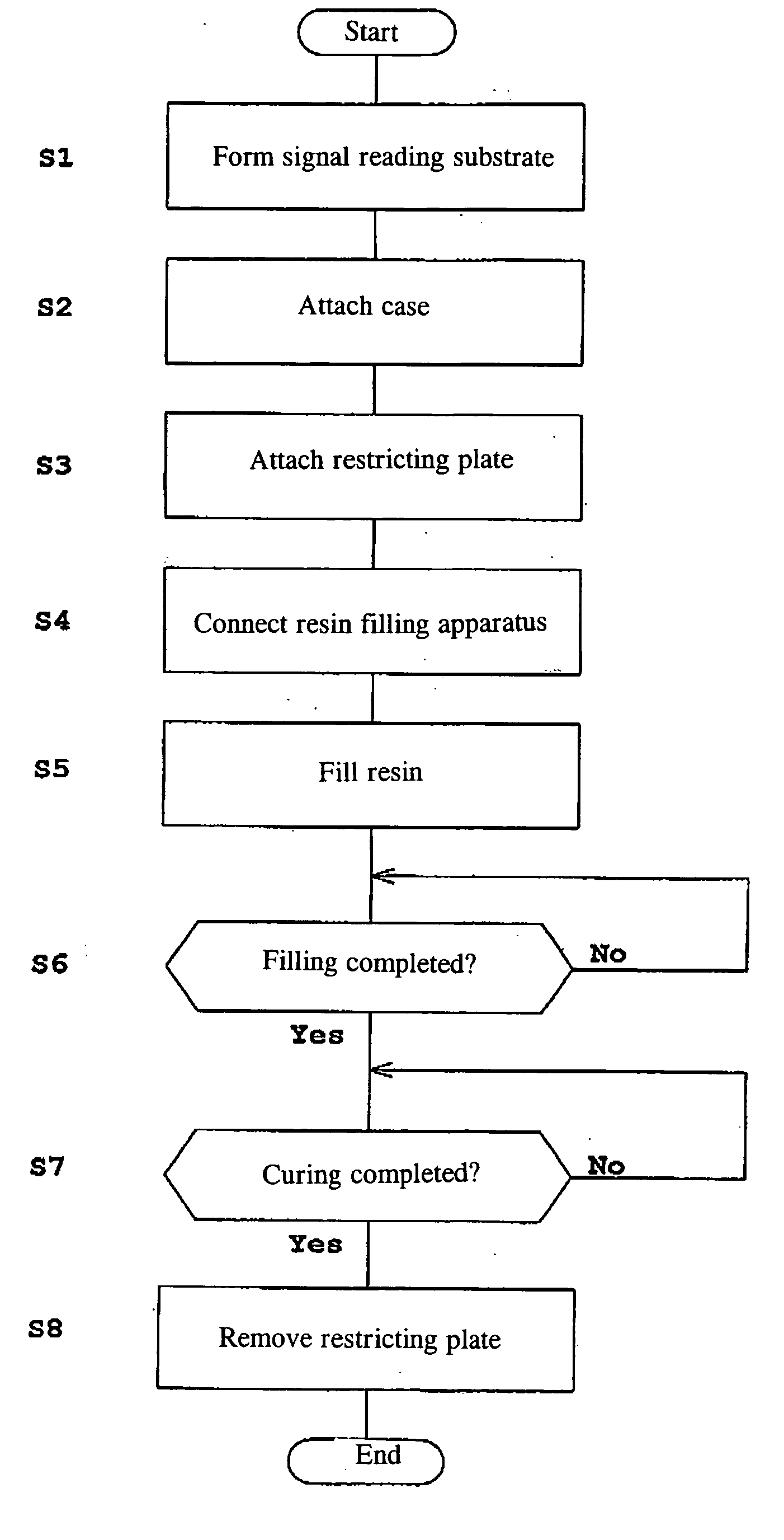
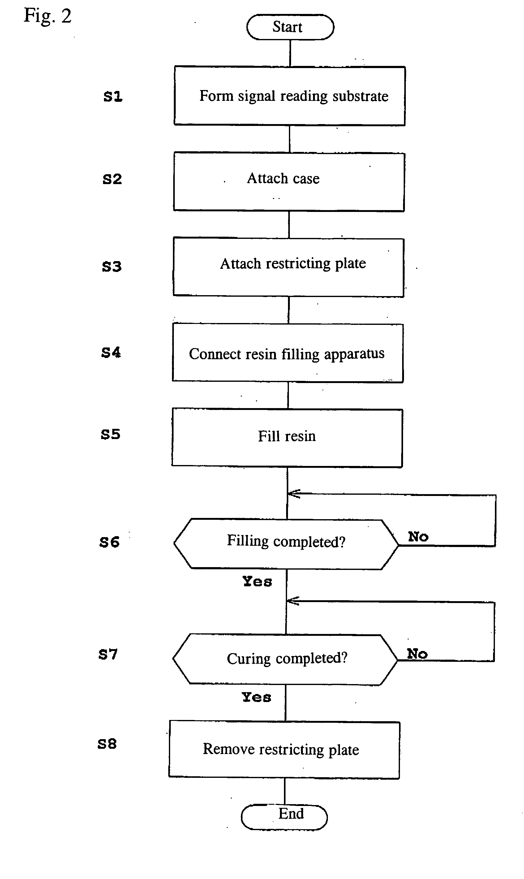

Image

  • Process for producing a flat panel radiation detector and a flat panel radiation detector
  • Process for producing a flat panel radiation detector and a flat panel radiation detector
  • Process for producing a flat panel radiation detector and a flat panel radiation detector

Examples


first embodiment

[0031] The first embodiment of the present invention will be described with reference to the drawings.

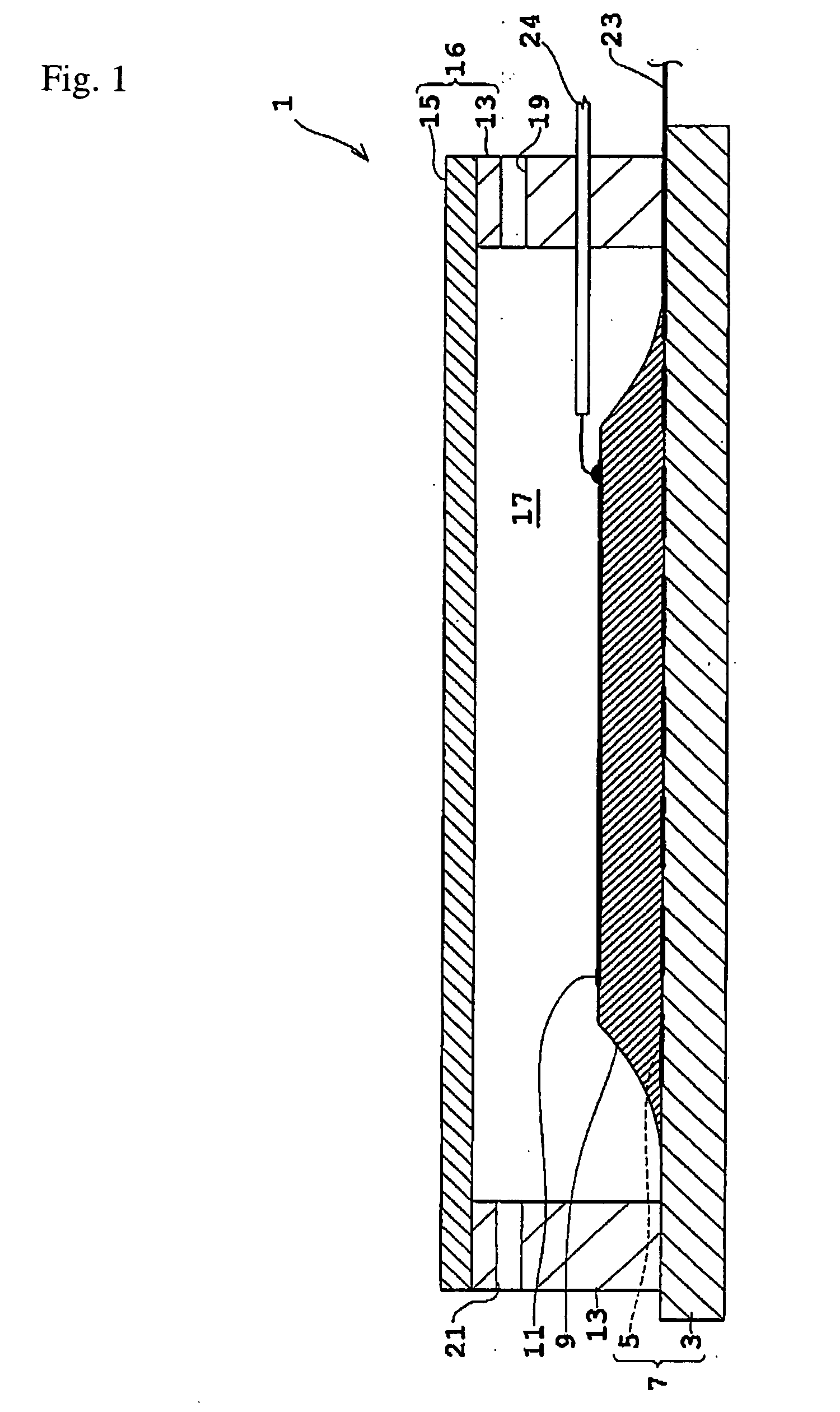
[0032]FIG. 1 is a profile showing the simplified structure of a flat panel radiation detector according to a first embodiment before the filling of the resin.

[0033] The flat panel radiation detector 1 is equipped with a signal reading substrate 7 forming a read out circuit 5 on a substrate 3 that is made from an insulating material such as glass. A radiation sensitive layer 9 that generates an electronic charge in response to an incidence of, for example, x ray is disposed on the signal reading substrate. A bias electrode 11 is disposed on the radiation sensitive layer. The radiation sensitive layer may be, for example, amorphous selenium (non-crystalline Se) or a semiconductor layer such as CdZnTe, CdTe, HgI2, PbI2 or the like. The thickness of the radiation sensitive layer is, for example, about 0.5-3 mm. For the bias electrode 11, metal layers such as gold (Au), aluminum (Al) a...

second embodiment

[0056] Next, the second embodiment of the present invention will be explained with reference to the figures.

[0057]FIG. 10 shows a step in the process for producing the flat panel radiation detector of the second embodiment and is a profile showing the step where the case is attached. FIG. 11 is a profile showing the state at the end of the filling of the resin. When the composition is similar to that described in the first embodiment, detailed explanation is omitted by using the same numerals.

[0058] In the first embodiment described above, the restricting plate 27 and the spacer 25 are used but the difference in the second embodiment is that these two are unified to make a restricting plate 39. The restricting plate 39 that is a restricting member in the present invention has a recess 41 formed on its bottom face. The recess 41 is shaped so that it fits against the shape of the upper plate 15 when it is expanded in response to the filling of the resin. Thus, the depth of the reces...


PUM


Abstract

Because a restricting plate 27 is disposed using a spacer 25, an upper plate 15 is allowed to expand upward when resin is injected, but unnecessary overexpansion is restricted by the restricting plate 27. Therefore the injection of a slightly larger amount of resin 37 does not cause a distortion or breakage of the upper plate 15 and a large amount resin 37 than the predetermined amount may be injected. As a result, damage to the upper plate 15 by the injection of the resin 37 and damage to the upper plate 15, the exfoliation of the radiation sensitive layer, and the like caused by the curing of the resin 37 may be prevented and damage to the flat panel radiation detector 1 may be prevented thereby.

Description

INCORPORATION BY REFERENCE [0001] The present application claims priority under 35 U.S.C. §119 to Japanese Patent Application No. 2004-169791 filed on Jun. 8, 2004. The content of the application is incorporated herein by reference in its entirety. BACKGROUND OF THE INVENTION [0002] The present invention relates to a flat panel radiation detector which is used for medical and industrial use and to a process for producing the same, wherein the flat panel radiation detector is composed: of a signal reading substrate on which a radiation sensitive layer that generates an electric charge with an incidence of radiation is mounted; an upper plate placed on top of the signal reading substrate facing the signal reading substrate across the radiation sensitive layer; and resin filling the space between the signal reading substrate and the upper plate. [0003] Formerly, in the process for producing this kind of the flat panel radiation detector (also called “FPD”), resin mold, i.e., filling wi...

Claims


Application Information

Patent Timeline
IPC IPC(8): H01L21/00H01L23/34G01T1/24H01L27/14H01L31/00H01L31/18H04N5/32
CPCH01L21/6715H01L31/0203H01L2924/0002H01L2924/00
Inventor SUZUKI, JUNICHINAGAFUNE, NOBUYASATO, KENJIYOSHIMUTA, TOSHINORISATO, TOSHIYUKI
Owner SHIMADZU CORP
Learn More