Apparatus and methods for delivering a closure device

a technology of opening and sealing device, applied in the direction of mechanical equipment, surgical staples, veterinary instruments, etc., can solve the problems of time-consuming and expensive procedures, requiring as much as an hour of physician's or nurse's time, and uncomfortable for patients

Inactive Publication Date: 2005-12-08
INTEGRATED VASCULAR SYST
View PDF99 Cites 117 Cited by
  • Summary
  • Abstract
  • Description
  • Claims
  • Application Information

AI Technical Summary

Benefits of technology

[0012] A carrier assembly is slidable on the elongate member, the carrier assembly including an inner carrier member, a middle pusher member, and, optionally, an outer skin, nested together. Each member may have an annular shape, and may include a connector on its proximal end. The pusher member may be disposed about the carrier member to define a space distal to the pusher member along an outer surface of the carrier member. The outer skin has a length, whereby the outer skin may extend over the space and / or contact an outer surface of the elongate member. In a preferred embodiment, the outer skin extends a short distance beyond a distal end of the carrier member, such that the outer skin is slidable along the elongate member.
[0019] In addition, the actuator assembly may also include an obturator or locator member that may be part of the actuator assembly or may be connected to the actuator assembly. A distal portion of the locator member may extend distally beyond the actuator members. In addition, the locator member has sufficient length such that the distal portion may extend beyond the distal end of the elongate member when the actuator assembly is connected to the elongate member. One or more positioning elements on the distal portion of the locator member may be movable from a collapsed configuration towards a transversely expanded configuration. A locking mechanism on the locator member and / or actuator assembly may releasably retain the positioning elements in the expanded configuration.

Problems solved by technology

This procedure, however, may be time consuming and expensive, requiring as much as an hour of a physician's or nurse's time.
It is also uncomfortable for the patient, and requires that the patient remain immobilized in the operating room, catheter lab, or holding area.
In addition, a risk of hematoma exists from bleeding before hemostasis occurs.
Such devices, however, may be difficult to position properly with respect to the vessel, which may be particularly significant since it is generally undesirable to expose the plug material, e.g., collagen, within the bloodstream, where it may float downstream and risk causing an embolism.
Percutaneous suturing devices, however, may require significant skill by the user, and may be mechanically complex and expensive to manufacture.
This device, however, requires that an anchor of the plug be positioned within the vessel, and therefore, may increase the risk of over-advancement of the plug itself into the vessel.
Such a device, however, may risk engagement between the loop and the surgical clip, thereby preventing the loop from being withdrawn from the vessel.

Method used


Image

  • Apparatus and methods for delivering a closure device
  • Apparatus and methods for delivering a closure device
  • Apparatus and methods for delivering a closure device

Examples


Embodiment Construction

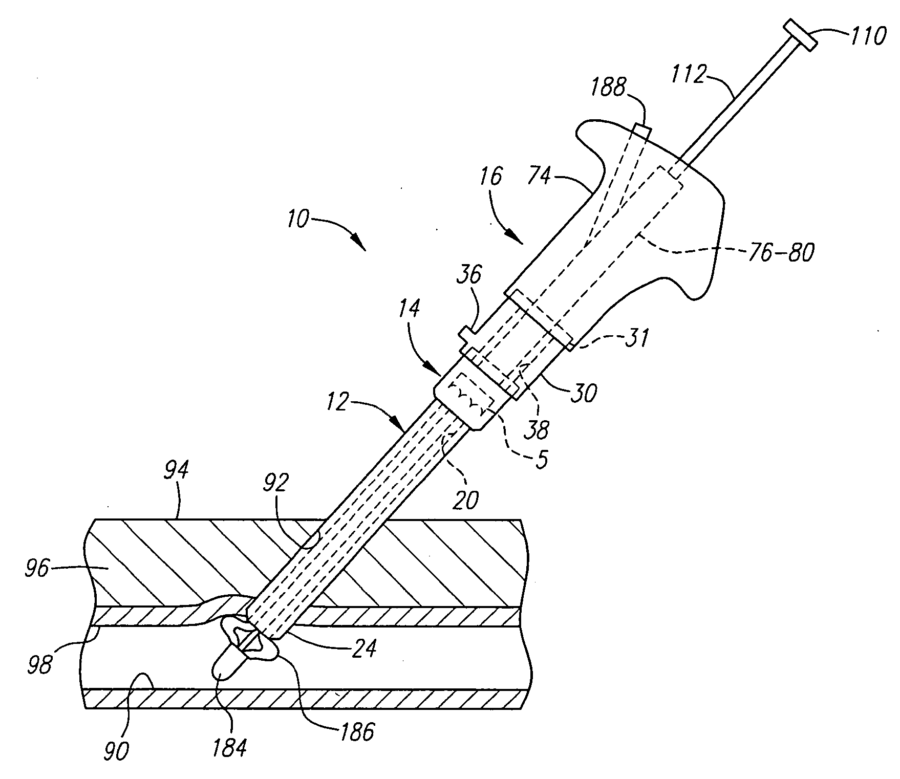
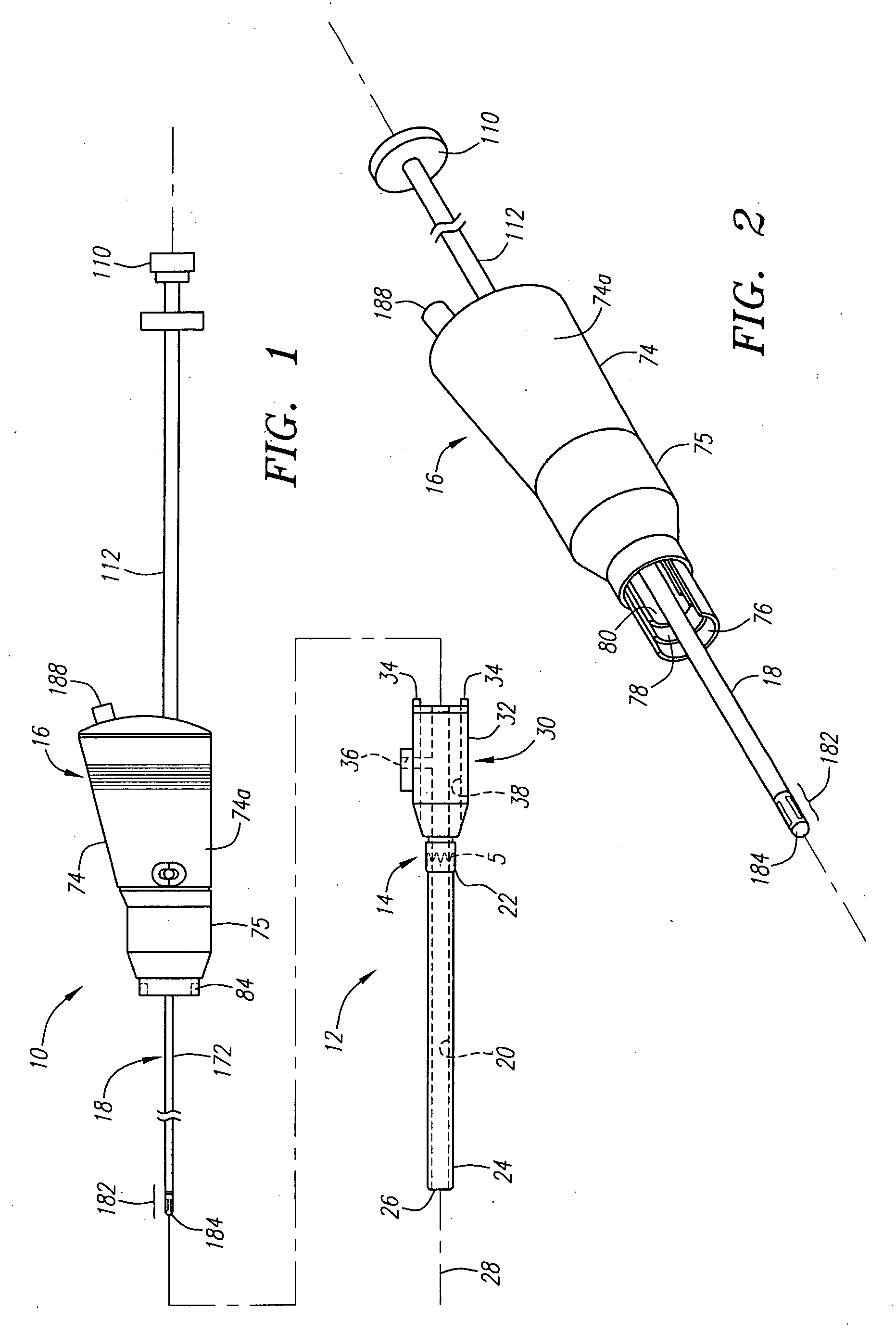
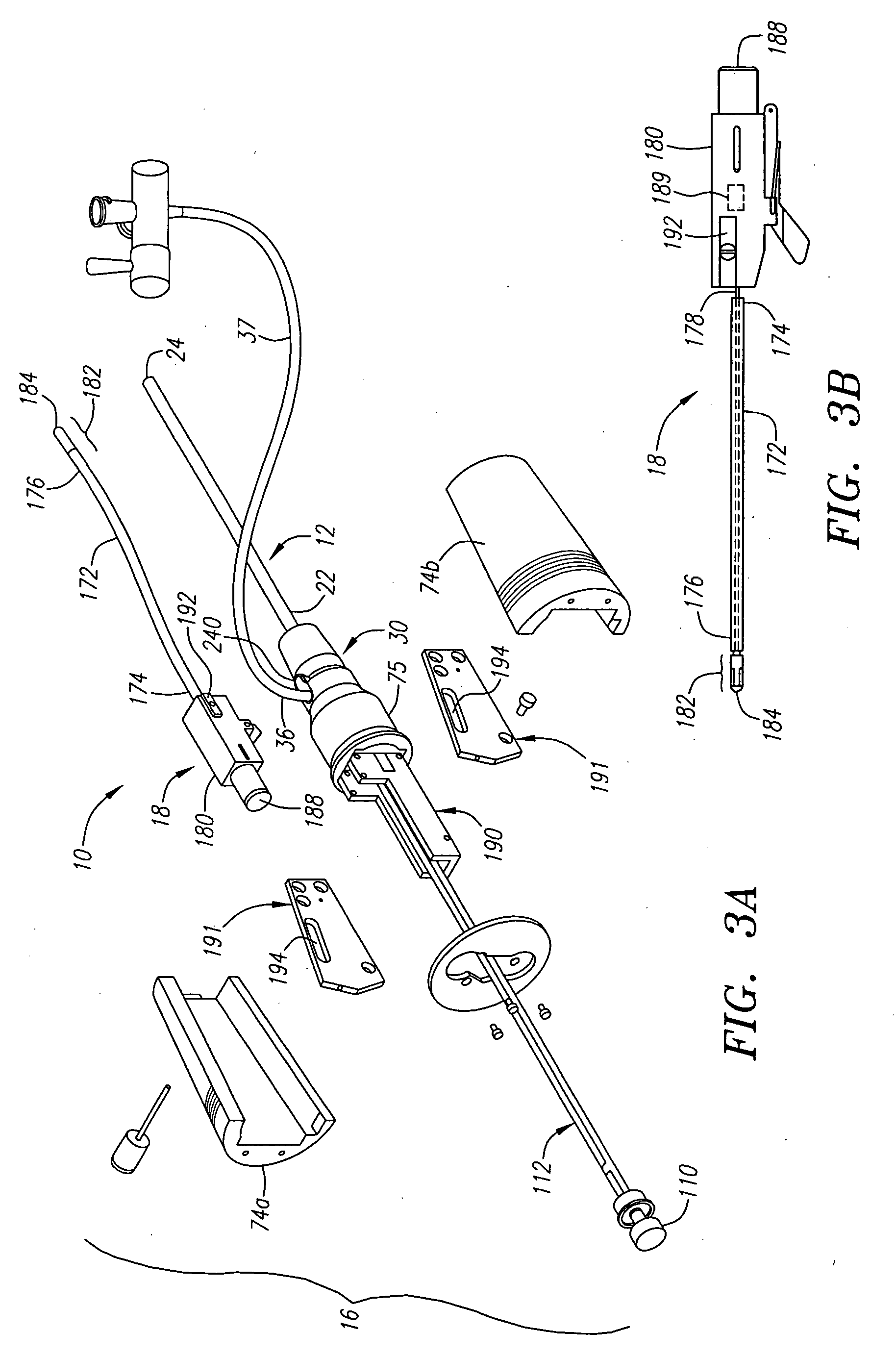
[0039] Turning to the drawings, FIGS. 1-4 show a first preferred embodiment of an apparatus 10 for delivering a closure element, such as a clip 5 (shown in phantom), into an opening through tissue for closing the opening (not shown). Generally, the apparatus 10 includes an introducer sheath 12, a housing or carrier assembly 14 slidably disposed on the sheath 12, and an actuator or actuator assembly 16 that is connectable to the introducer sheath 12. In addition, the apparatus 10 may also include a locator member or obturator 18, which may be part of the actuator assembly 16, as shown in FIGS. 1-3. Alternatively, the apparatus 310 may include an obturator 318 that is a separate subassembly that may be inserted through an actuator assembly 316 and / or sheath 312, as shown in FIGS. 11A and 11B.

[0040] As best seen in FIGS. 1 and 4, the introducer sheath 12 is generally a substantially flexible or semi-rigid tubular member including a lumen 20 extending along a longitudinal axis 28 betwe...


PUM


Abstract

An apparatus for delivering a clip to close an opening through tissue includes a sheath and a carrier assembly including a clip therein that is slidable on the sheath. An actuator assembly is connectable to the sheath, and telescoping actuator members extend from the handle that are connectable to the carrier assembly for advancing the carrier assembly along the sheath. An obturator on the actuator assembly includes splines that may be deployed beyond a distal end of the sheath, and expanded to a transverse expanded configuration for positioning the sheath before deploying the clip. The actuator members include cooperating detents that selectively release the actuator members as the carrier assembly reaches predetermined positions along the sheath for deploying the clip from the carrier assembly, and that collapse the splines to allow removal of the apparatus after deploying the clip.

Description

[0001] This application is a continuation of co-pending application Ser. No. 10 / 081,723, filed Feb. 21, 2002, which is a continuation-in-part of co-pending application Ser. No. 09 / 732,835, filed Dec. 7, 2000, now U.S. Pat. No. 6,780,197, which is a continuation-in-part of co-pending application Ser. No. 09 / 610,238, filed Jul. 5, 2000, now U.S. Pat. No. 6,391,048, which is a continuation-in-part of co-pending application Ser. No. 09 / 478,179, filed Jan. 5, 2000, now U.S. Pat. No. 6,197,042, the disclosures of which are expressly incorporated herein by reference.FIELD OF THE INVENTION [0002] The present invention relates generally to apparatus and methods for closing and / or sealing openings through tissue, and more particularly to apparatus and methods for delivering a closure element for closing a puncture in a blood vessel or other body lumen formed during a diagnostic or therapeutic procedure. BACKGROUND [0003] Catheterization and interventional procedures, such as angioplasty or st...

Claims


Application Information

Patent Timeline
Patent Type & Authority Applications(United States)
IPC IPC(8): A61B17/00A61B17/064A61B17/08A61B17/128A61B19/00
CPCA61B17/0057A61B17/064A61B17/083A61B17/128A61B2017/00004A61B2017/00637A61B2017/00668A61B2017/00672A61B2017/00862A61B2017/0641A61B90/39
Inventor BELEF, W. MARTINALDRICH, WILLIAM N.CARLEY, MICHAEL T.JABBA, RONALD J,SALMON, STEPHEN M.PANTAGES, ANTHONYSAGASTEGUI, JAVIER
Owner INTEGRATED VASCULAR SYST
Why Eureka
Try Eureka