Prosthetic intervertebral spinal disc with integral microprocessor

a technology of intervertebral discs and microprocessors, applied in the field of artificial, constrained motion spinal discs, can solve problems such as pain or paralysis in the area of its distribution, damage to the spinal disc, and detrimental phenomena

Active Publication Date: 2005-12-08
THEKEN SPINE
View PDF99 Cites 286 Cited by
  • Summary
  • Abstract
  • Description
  • Claims
  • Application Information

AI Technical Summary

Problems solved by technology

Spinal discs may be damaged or displaced due to trauma or disease.
This may in turn press upon the spinal nerve that exits the vertebral canal through the partially obstructed foramen, causing pain or paralysis in the area of its distribution.
First, it may be necessary to remove the involved disc surgically and fuse the two adjacent vertebrae together.
In many long term patients of fused spinal segments, a detrimental phenomena has been observed whereby discs adjacent to the fused spinal segment will have increased motion and stress due to the increased stiffness of the fused segment.
No matter which of the artificial intervertebral disc replacements are used, all lack memory storage and processing capabilities that would assist a doctor in diagnosing a patient's spinal condition and the performance of the artificial disc once implanted.
This type of feedback is limited due to the lack of ability of the patient to properly describe sensations or feelings which may be coming from their back, and may further be limited by a lack of candor on the part of the patient who may fail to tell the doctor about activities the patient has engaged in that are not appropriate for the artificial disc.

Method used


Image

  • Prosthetic intervertebral spinal disc with integral microprocessor
  • Prosthetic intervertebral spinal disc with integral microprocessor
  • Prosthetic intervertebral spinal disc with integral microprocessor

Examples


first embodiment

[0078] Referring now to FIG. 13, there is illustrated the output of a transducers 202a-202c responsive to movements of the intervertebral disc 100 caused by movement of the patient. The data from the transducers may be stored in a number of fashions. In a first embodiment, a 3D resultant vector is generated from the outputs of each of the transducers. The resultant slope and magnitude of the vector may then be stored in memory if these values exceed certain predetermined thresholds. If memory storage is limited a determination and deletion of a smallest presently stored resultant vector may be made. This will create space for the storage of characteristics relating to the new larger resultant vector.

second embodiment

[0079] In a second embodiment, the entire waveform output from each of the transducers 202a-202c may be stored in memory for a selected period of time. In this situation the thresholds relating to the occurrence of an event that required the storage of data would have to be set sufficiently high that data was only stored a few times per day. If waveforms were stored too frequently, the memory space would quickly be exhausted and battery power would be depleted.

third embodiment

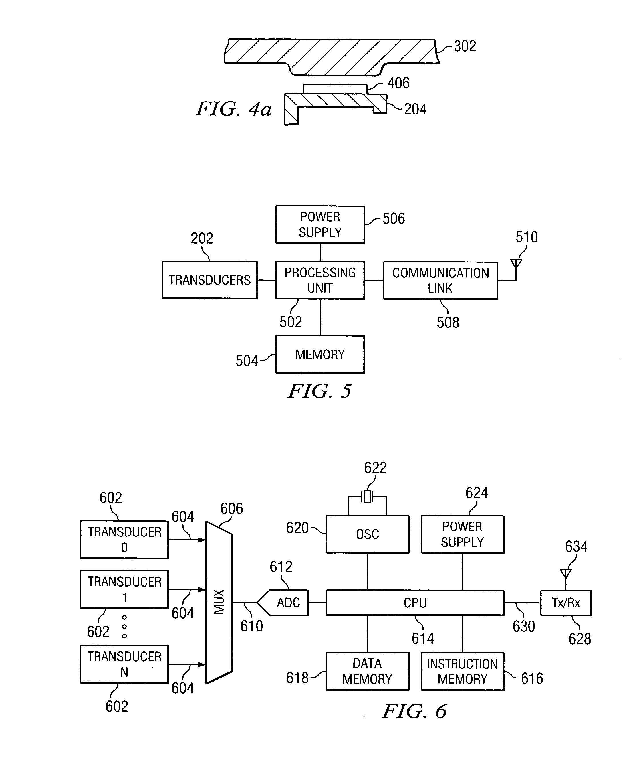
[0080] In a third embodiment, rather than storing the entire output waveform 1302 within the memory 504, the central processing unit 502 generates various characteristics describing the output waveform 1302. These parameters include a maximum value 1304 representing the peak output of the transducer waveform 1302 and the slope value 1306 represents the maximum slope of the output waveform 1302 of the transducer and provides an indication of the intensity of the pressures being placed between the upper plate 106 and lower plate 108 of the artificial disc 100.

[0081] The central processing unit 502 includes two separate modes for transmitting data using its communications link 508 and antenna 510. The operation of these modes are more fully illustrated in the flow diagram of FIG. 14. After occurrence of the power on self test at step 1402, the CPU enters the sleep mode at step 1404. Inquiry step 1406 determines whether or not a waking requirement has been initiated for the sleep mode. ...


PUM


Abstract

A device for storing data related to movement of a prosthetic implant includes at least one transducer for generating at least one real time movement signal responsive to movement within the prosthetic implant. A processor generates movement data parameters and associated time stamps in response to the real time movement signal. The generated data parameters and time stamps are stored within a memory associated with the processor. A communications link may be used to selectively access the movement data parameters and the time stamps in the memory from an external source.

Description

TECHNICAL FIELD OF THE INVENTION [0001] This invention relates to an artificial, constrained motion spinal disc for replacing intervertebral discs in the lower back, and more particularly, to an artificial disc including processing and memory storage capabilities. BACKGROUND OF THE INVENTION [0002] The human spine is composed of many vertebra stacked one upon the other, with an intervertebral disc between each pair of adjacent vertebra. The discs act as cartilaginous cushions and shock absorbers. The spinal cord runs in a bony canal formed by successive openings in these bones. The spinal nerves exit the spinal cord between pairs of vertebrae and supply nerves and nerve signals to and from other body structures. [0003] The vertebral disc is a complex joint both anatomically and functionally. It is composed of three component structures: the nucleus pulposus; the annulus fibrosis, and the vertebral end plates. The biomedical composition and anatomical arrangements within these compon...

Claims


Application Information

Patent Timeline
Patent Type & Authority Applications(United States)
IPC IPC(8): A61B5/11A61F2/00A61F2/02A61F2/28A61F2/30A61F2/44A61F2/46
CPCA61F2/442A61F2002/30069A61F2002/30087A61F2002/30133A61F2002/30462A61F2002/30563A61F2002/3067A61F2002/4666A61F2220/0075A61F2230/0015A61F2250/0002Y10S623/914
Inventor NAVARRO, RICHARD ROBERTCOLE, CHRISTOPHER PAULTHEKEN, RANDALL RAYMOND
Owner THEKEN SPINE
Why Eureka
Try Eureka