Engine valve actuator

a technology of actuator and engine, which is applied in the direction of valve arrangement, non-mechanical valve, machines/engines, etc., can solve the problems of slowing the vehicle, discharging the kinetic energy of the moving vehicle, damage to the exhaust valve, etc., and achieve the effect of limiting the movement of the piston

Inactive Publication Date: 2005-12-15
CATERPILLAR INC
View PDF3 Cites 19 Cited by
  • Summary
  • Abstract
  • Description
  • Claims
  • Application Information

AI Technical Summary

Benefits of technology

[0011] In another aspect, the present disclosure is directed to a method of limiting the stroke of an actuator piston associated with an engine valve of an internal combustion engine. Pressurized fluid is provided to a housing that defines an opening and has a protrusion extending into the opening. The pressurized fluid is directed through the opening to a piston adapted to operatively engage an engine valve. The piston has a bore adapted to receive the protrusion. The pressurized fluid acts on the piston to move the piston relative to the housing to thereby open the engine valve. The pressurized fluid is allowed to flow from the opening in the housing through a fluid passageway connecting the bore of the piston with a chamber in the piston to thereby limit the movement of the piston.

Problems solved by technology

The compression release braking system releases the compressed air from the combustion chambers to the environment to thereby dissipate the kinetic energy of the moving vehicle and slow the vehicle.
Contact between the exhaust valve and the piston can result in damage to the exhaust valve, which may detract from engine performance when conventional engine operation is resumed.
Thus, the compression release braking system described in U.S. Pat. No. 5,161,501 to Hu is relatively inflexible and does not provide for individual valve actuator adjustment.

Method used


Image

  • Engine valve actuator
  • Engine valve actuator
  • Engine valve actuator

Examples


Embodiment Construction

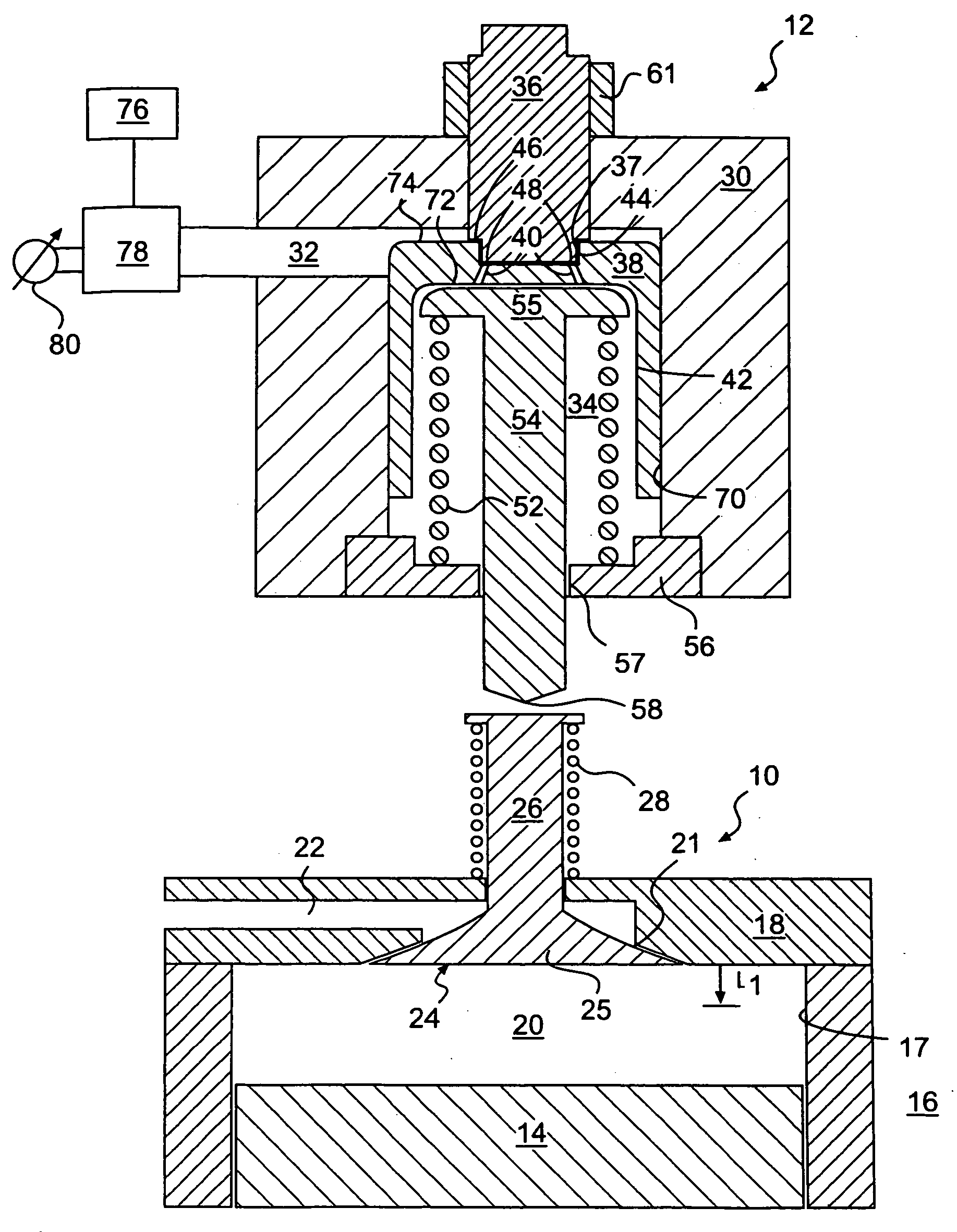
[0016] An exemplary embodiment of an engine valve actuator 12 for an internal combustion engine 10 is illustrated in FIG. 1. Engine 10 includes an engine block 16 having a cylinder 17 that defines a combustion chamber 20. A cylinder head 18 may be engaged with engine block 16 to cover cylinder 17.

[0017] As also shown, a piston 14 may be disposed within cylinder 17. Piston 14 is adapted to reciprocate between a bottom-dead-center position and a top-dead-center position within cylinder 17. Piston 14 may be connected to a crankshaft (not shown) such that a rotation of the crankshaft causes piston 14 to reciprocate between the bottom-dead-center position and the top-dead-center position in cylinder 17. In addition, a reciprocating movement of piston 14 between the bottom-dead-center position and the top-dead-center position within cylinder 17 will cause a corresponding rotation of the crankshaft.

[0018] Engine 10 may, for example, operate in a conventional four stroke diesel cycle. In ...


PUM


Abstract

An engine valve actuator for an internal combustion engine is provided. The engine valve actuator includes a housing having an opening and a first fluid passageway leading to the opening. An adjustment member is disposed in the housing and includes a protrusion that extends into the opening of the housing. A piston is disposed in the opening of the housing and has a bore adapted to receive the protrusion, a chamber, and a second fluid passageway that connects the bore with the chamber. The piston is adapted to move in a first direction relative to the housing in response to an introduction of pressurized fluid into the first fluid passageway. The piston moves in the first direction until the protrusion substantially withdraws from the bore. A push rod is operatively engaged with the piston such that movement of the piston in the first direction causes a corresponding movement of the push rod to thereby engage and open the engine valve.

Description

TECHNICAL FIELD [0001] The present disclosure is directed to an engine valve actuator and, more particularly, the present disclosure is directed to a stroke limiter for an engine valve actuator. BACKGROUND [0002] A vehicle, such as, for example, an on or off highway truck, may include a compression release braking system that assists a conventional braking system in reducing the speed of the vehicle. The compression release braking system allows an internal combustion engine to convert the kinetic energy of the moving vehicle into compressed air in the combustion chambers of the engine. The compression release braking system releases the compressed air from the combustion chambers to the environment to thereby dissipate the kinetic energy of the moving vehicle and slow the vehicle. [0003] A compression release braking system typically cooperates with a valve actuation system connected with the engine. The compression release braking system opens the exhaust valves of the engine when...

Claims


Application Information

Patent Timeline
Patent Type & Authority Applications(United States)
IPC IPC(8): F01L13/06F01L9/02F01L1/26F01L9/10
CPCF01L1/26F01L9/02F01L13/065F01L9/10
Inventor CHANG, DAVID Y.
Owner CATERPILLAR INC
Why Eureka
Try Eureka