Linear compressor and control method thereof

a linear compressor and control method technology, applied in the direction of dynamo-electric converter control, motor/generator/converter stopper, piston pump, etc., can solve the problem that the output voltage of the position detection circuit of the conventional linear compressor does not exist, and achieve the effect of accurately controlling the reciprocal movement of the piston

Inactive Publication Date: 2005-07-14
SAMSUNG ELECTRONICS CO LTD
View PDF14 Cites 6 Cited by
  • Summary
  • Abstract
  • Description
  • Claims
  • Application Information

AI Technical Summary

Benefits of technology

[0013] It is an aspect of the present invention to provide a linear compressor capable of controlling a reciprocal movement of a piston accurately.

Problems solved by technology

However, the output voltage of the position detection circuit of the conventional linear compressor does not have a linear property in which the output voltage is proportional to the position of the piston because of a length of the core 103, temperature, pressure, and a heat noise of a circuit.
However, if it has a response property represented by a line ‘b’ because of an external influence, there could be a problem that the piston collides with a valve in a high power operation as the measured position of the piston differs from an actual position of the piston.

Method used


Image

  • Linear compressor and control method thereof
  • Linear compressor and control method thereof
  • Linear compressor and control method thereof

Examples


Embodiment Construction

[0049] Reference will now be made in detail to the aspects of the present invention, examples of which are illustrated in the accompanying drawings, wherein like reference numerals refer to like elements throughout. The aspects are described below in order to explain the present invention by referring to the figures.

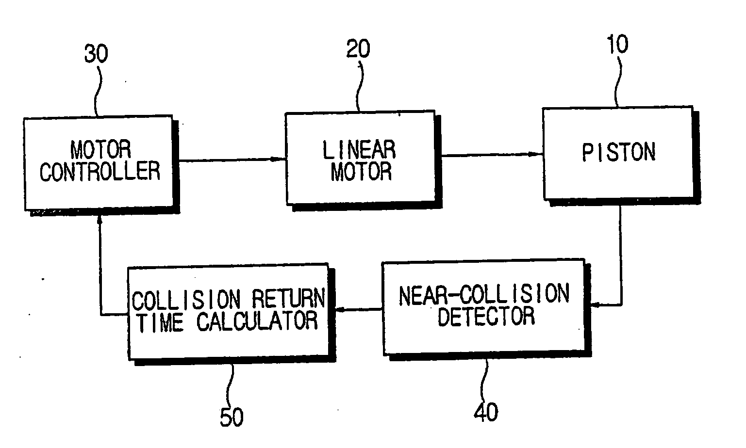
[0050]FIG. 4 is a schematic configuration block diagram of a linear compressor according to an aspect of the present invention. As shown in FIG. 4, a linear compressor comprises a piston 10, a linear motor 20, a motor controller 30, a near-collision detector 40, and a collision return time calculator 50. The piston 10 is connected to the linear motor 20 and reciprocates according to a compression cycle and an expansion cycle.

[0051] The motor controller 30 controls the linear motor 20 so that a stroke of the piston 10 varies according to power, such as a top dead center and a bottom dead center position of the piston. The top dead center during a high power operation is...


PUM


Abstract

A linear compressor having a reciprocating piston, a linear motor driving the piston, and a motor controller to vary magnitude of a stroke of the piston according to power, including: a near-collision detector detecting whether the piston passes a near-collision position spaced from a top dead center according to a predetermined high power with a predetermined high power distance; and a collision return time calculator calculating a near-collision position return time taking for the piston to return to the near-collision position on a basis of the detection of the near-collision detector according to compression and expansion cycles, and wherein the motor controller decreases a driving force of the linear motor if the near-collision position return time is greater than a predetermined allowance time per power, and increases the driving force of the linear motor if the near-collision position return time is less than the predetermined allowance time per power.

Description

CROSS-REFERENCE TO RELATED APPLICATION [0001] This application claims the benefit of Korean Patent Application No. 2004-0001447, filed Jan. 9, 2004, in the Korean Intellectual Property Office, the disclosure of which is incorporated herein by reference. BACKGROUND OF THE INVENTION [0002] 1. Field of the Invention [0003] The present invention relates to a linear compressor and a control method thereof which can control the reciprocal movement of a piston more accurately. [0004] 2. Description of the Related Art [0005] A linear compressor is widely used to compress coolant in a cooling cycle of a refrigerator. The linear compressor measures a magnitude of a stroke of a piston, and adjusts current applied to a driving motor on a basis of the measured stroke magnitude to control an operation of the piston. FIG. 1 is a cross-sectional view of a sensor structure for detecting a position of the piston of a conventional linear compressor. As shown in FIG. 1, a sensor structure for a positio...

Claims


Application Information

Patent Timeline
Patent Type & Authority Applications(United States)
IPC IPC(8): F04B17/04F04B35/04F04B49/06H02P25/06
CPCF04B35/045H02P25/06H02P6/006F04B49/065E03D5/105E03D13/005
Inventor KIM, HYO-SUK
Owner SAMSUNG ELECTRONICS CO LTD
Why Eureka
Try Eureka