
Heat exchange device and method

a heat exchange device and heat exchange technology, applied in the direction of heat exchange modification, indirect heat exchangers, lighting and heating apparatus, etc., can solve the problem of less effective cooling, and achieve the effect of improving heat transfer

Inactive Publication Date: 2005-12-15
PRATT & WHITNEY CANADA CORP
View PDF26 Cites 3 Cited by
  • Summary
  • Abstract
  • Description
  • Claims
  • Application Information

AI Technical Summary

Benefits of technology

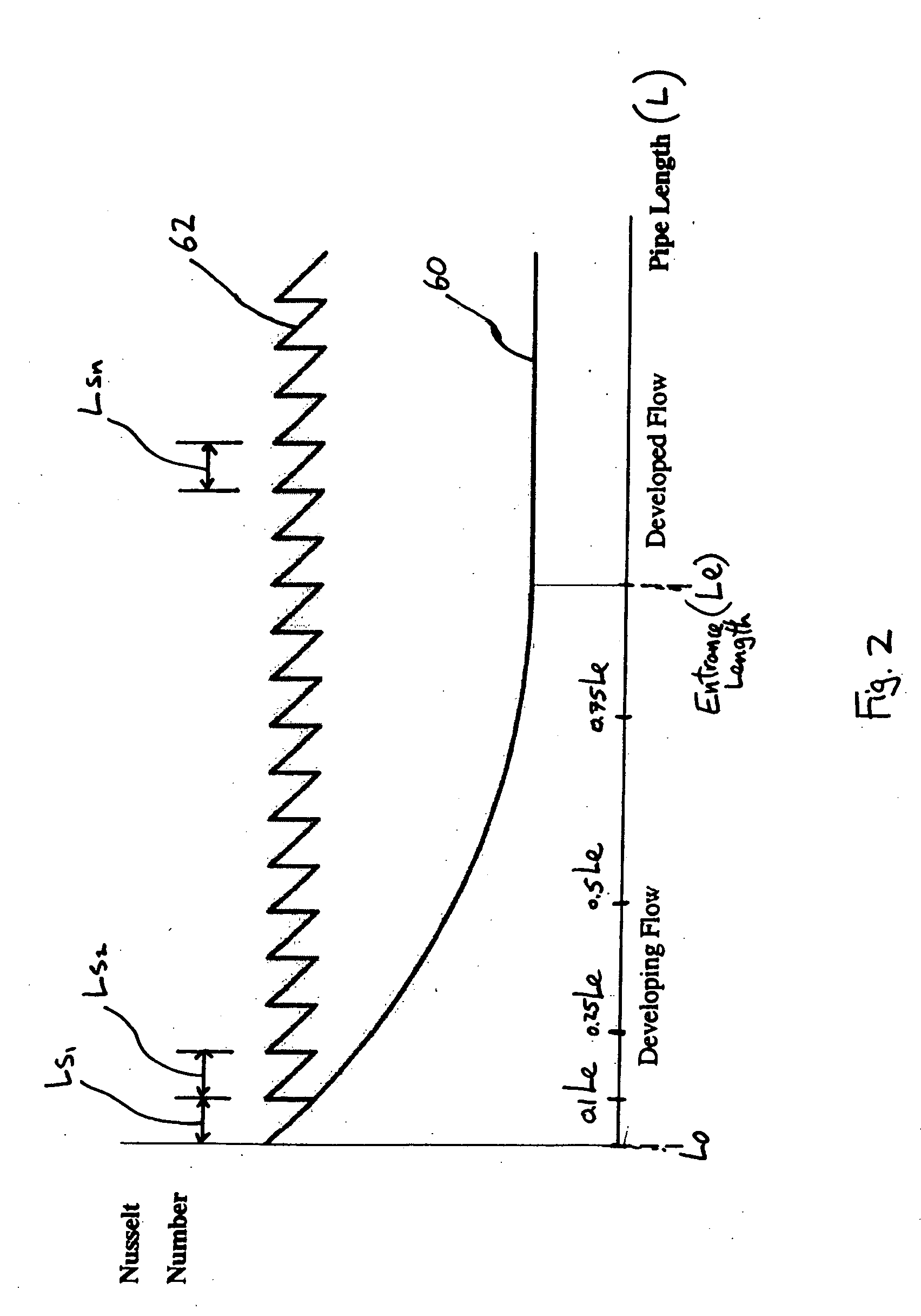
[0004] In accordance with the present invention there is provided a heat exchange device comprising a body defining at least one tortuous passage adapted to direct a heat transfer fluid therethrough, said passage having at least a plurality of successive segments in serial fluid flow communication, each of said segments having a length less than a length required for said fluid to achieve a fully developed laminar flow therein, thereby increasing convective heat transfer efficiency by causing a pipe inlet effect throughout said fluid flow passage.
[0005] In accordance with the present invention, there is also provided a method of improving heat transfer between a body and a fluid passing through a passage and adjacent the body, the method comprising the steps of: determining a threshold segment geometry, said threshold segment geometry being a passage length required for said fluid travelling through said passage to become fully developed laminar flow therein; providing said passage adjacent the body, the passage having a plurality of segments in serial fluid flow communication, each segment having geometry relative to said threshold segment geometry such that fluid passing through said segment cannot become fully developed laminar flow; and directing said fluid through said passage such that a developing flow is maintained in said segments.
[0006] There is further provided, in accordance with the present invention, a method of improving heat transfer between a body and a fluid passing through a passage adjacent the body, the method comprising the steps of: selecting a passage geometry having a plurality of successive segments, the passage geometry selected relative to the fluid to provide a desired Nusselt number for each of said successive segments, wherein said desired Nusselt is provided in a range between a Nusselt number corresponding to an inlet flow into the segment and a Nusselt number corresponding to a fully developed laminar flow in the segment; providing a passage comprised of said passage geometry; and directing the fluid through the passage.

Problems solved by technology

However, small equipment for example may require smaller cooling channels, but the small dimensions of such cooling channels can make cooling less effective, particularly when the cooling fluid is viscous (e.g. oil) and the fluid velocities are low.

Method used


Image

  • Heat exchange device and method
  • Heat exchange device and method
  • Heat exchange device and method

Examples


Embodiment Construction

[0016] The present invention has application in a wide variety of environments, however the skilled reader will appreciate that, although the invention may be adequately described with reference to a single environment (such as the electric machine described below), application of the invention is by no means limited to the specific example described. The following example is therefore but one of many applications to which the invention may be applied.

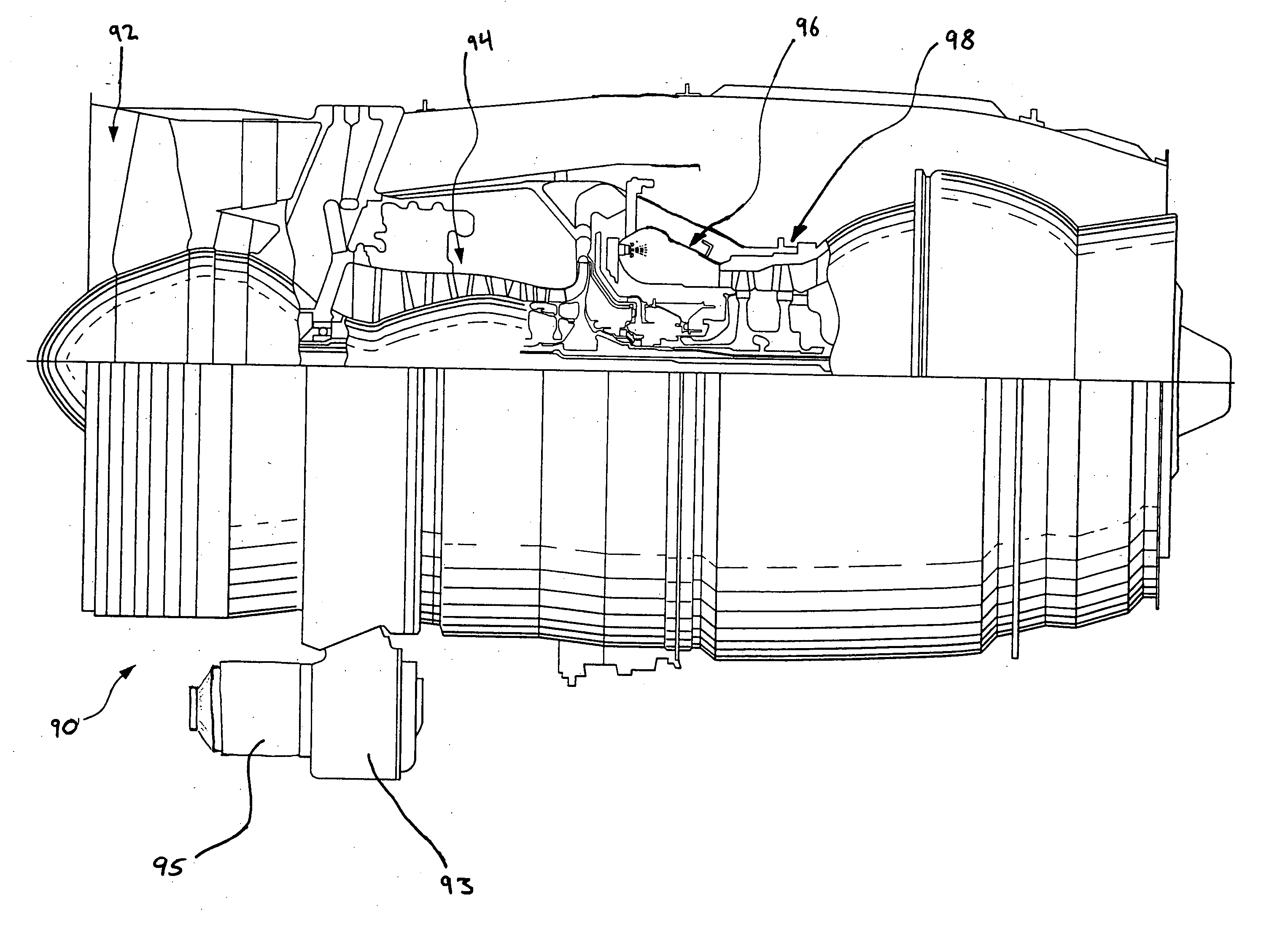
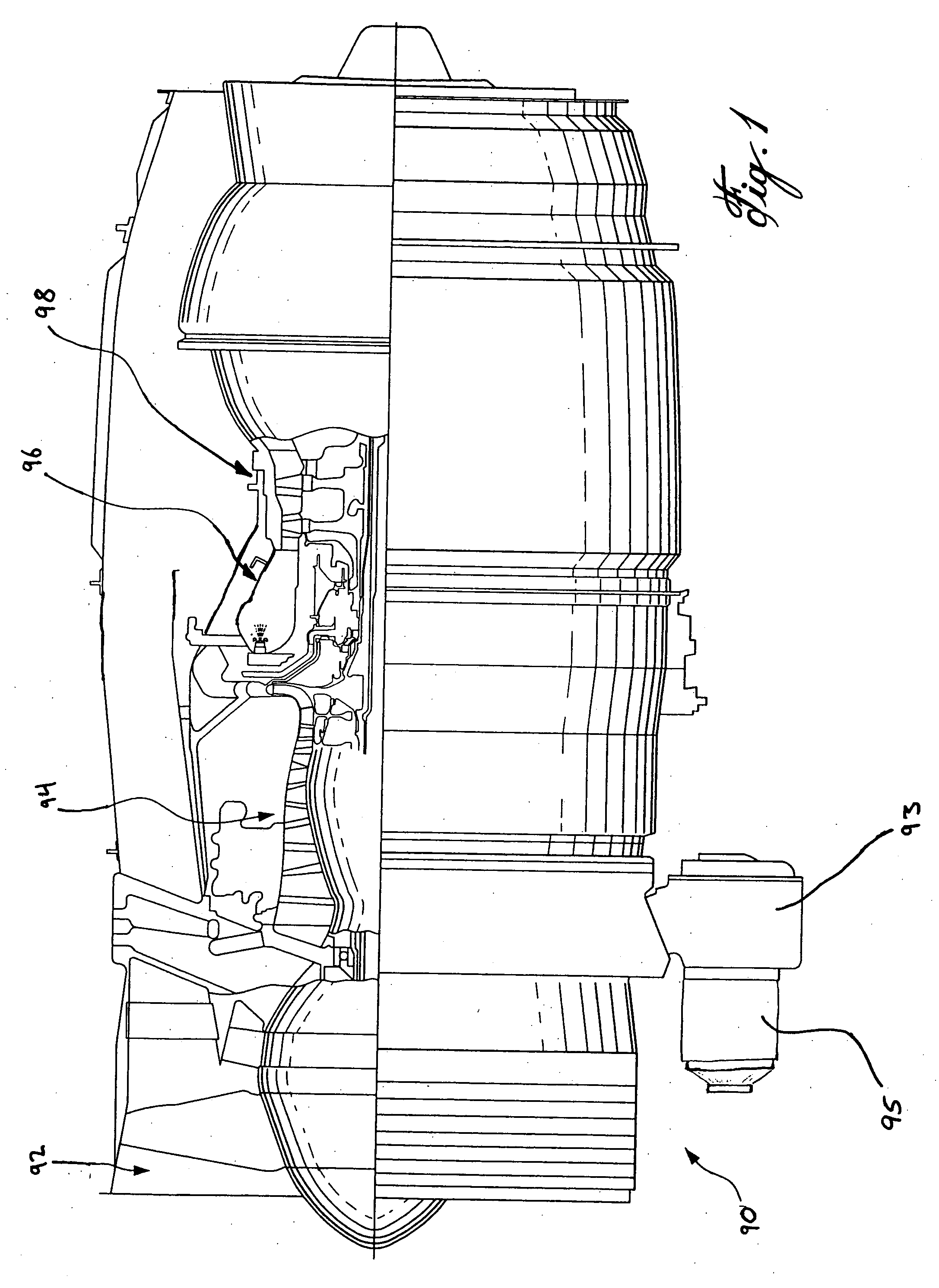
[0017]FIG. 1 illustrates a gas turbine engine 90 of a type preferably provided for use in subsonic flight, generally comprising in serial flow communication a fan 92 through which ambient air is propelled, a multistage compressor 94 for pressurizing the air, a combustor 96 in which the compressed air is mixed with fuel and ignited for generating an annular stream of hot combustion gases, and a turbine section 98 for extracting energy from the combustion gases. An accessory gearbox 93 is provided to drive accessories such as oil and fu...


PUM


Abstract

A heat exchange device comprising a fluid flow passage having a plurality of successive segments in fluid flow communication with one another, the segments being adapted to maintain a developing flow therein and thereby improve heat transfer.

Description

TECHNICAL FIELD [0001] The present invention relates generally to a method and device for improving heat transfer. BACKGROUND OF THE ART [0002] Heat exchange devices typically direct a coolant fluid through cooling passages to exchange heat between the surrounding body and the fluid by convective heat transfer. However, small equipment for example may require smaller cooling channels, but the small dimensions of such cooling channels can make cooling less effective, particularly when the cooling fluid is viscous (e.g. oil) and the fluid velocities are low. Therefore, improved heat exchange devices are needed. SUMMARY OF THE INVENTION [0003] One aspect of the present invention provides an improved heat exchange device and a method for improved heat transfer between a body and an adjacent fluid flow. [0004] In accordance with the present invention there is provided a heat exchange device comprising a body defining at least one tortuous passage adapted to direct a heat transfer fluid t...

Claims


Application Information

Patent Timeline
IPC IPC(8): F28F13/00H02K3/24F28F13/06H02K3/22F02C7/32F28F7/00F02C7/268H05K7/20H01L23/46
CPCF02C7/268F02C7/32F28F13/06H02K3/22F28D2021/0026
Inventor BRAND, JOSEPH HORACE
Owner PRATT & WHITNEY CANADA CORP
Learn More