
Structure for a cable connection head

a cable connection and cable head technology, applied in the direction of cable termination, wellbore/well accessories, survey, etc., can solve the problems of poor insulation or corrosion of the metal connection part, the most important and difficult part of the head body, and the introduction of the sheathed cables of the well logging cable to the head body, so as to eliminate any possibility of corrosion of the connector metal section, the effect of high viscosity and low viscosity

Inactive Publication Date: 2005-12-15
JAPAN PETROLEUM EXPLORATION CO LTD
View PDF3 Cites 24 Cited by
  • Summary
  • Abstract
  • Description
  • Claims
  • Application Information

AI Technical Summary

Benefits of technology

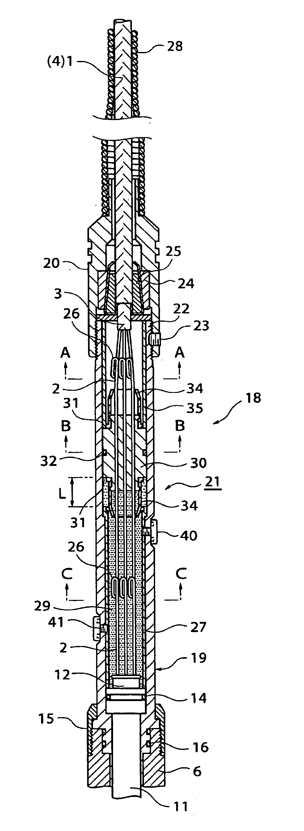
[0024] The structure of the cable connection head according to the present invention uses as an insulating material a smooth insulating oil with a generally low viscosity instead of a high viscosity grease where air bubbles are easily entrained and where channels are formed for the entry of borehole fluid into the bottom head body, so when filling the insulating oil into the bottom head body, no air bubbles are liable to be entrained in the insulating oil. Therefore, the borehole fluid is not liable to enter into the bottom head body even with long, continuous use of the measuring device, the insulating property of the core conductors of the sheathed cables will not drop, and it is possible to eliminate any possibility of corrosion of the connector metal section in the cable connection head.
[0025] The low viscosity, smooth insulating oil according to the present invention flows to the outside, but in the present invention, leakage can be prevented by the movable sealing member (that is, the lid member). In particular, at a borehole depth of several thousand meters, an extremely large pressure difference occurs between the bottom side of the movable sealing member at the oil filled side and the top side of the movable sealing member at the borehole fluid side. Due to this, the movable sealing member would presumably have to be made stronger and borehole fluid would possibly penetrate past the movable sealing member. In the present invention, however, the movable sealing member can move in the head body due to the pressure difference, so the movable sealing member may be constructed even not being able to withstand a large pressure. Further, the pressure difference above and below the movable sealing member falls along with the movement, so it is possible to prevent the borehole fluid from reaching the location of the connector metal section at the bottom side of the movable sealing member over a long term. BEST MODE FOR WORKING THE INVENTION
[0026] Below, embodiments of the present invention will be explained with reference to the drawings.
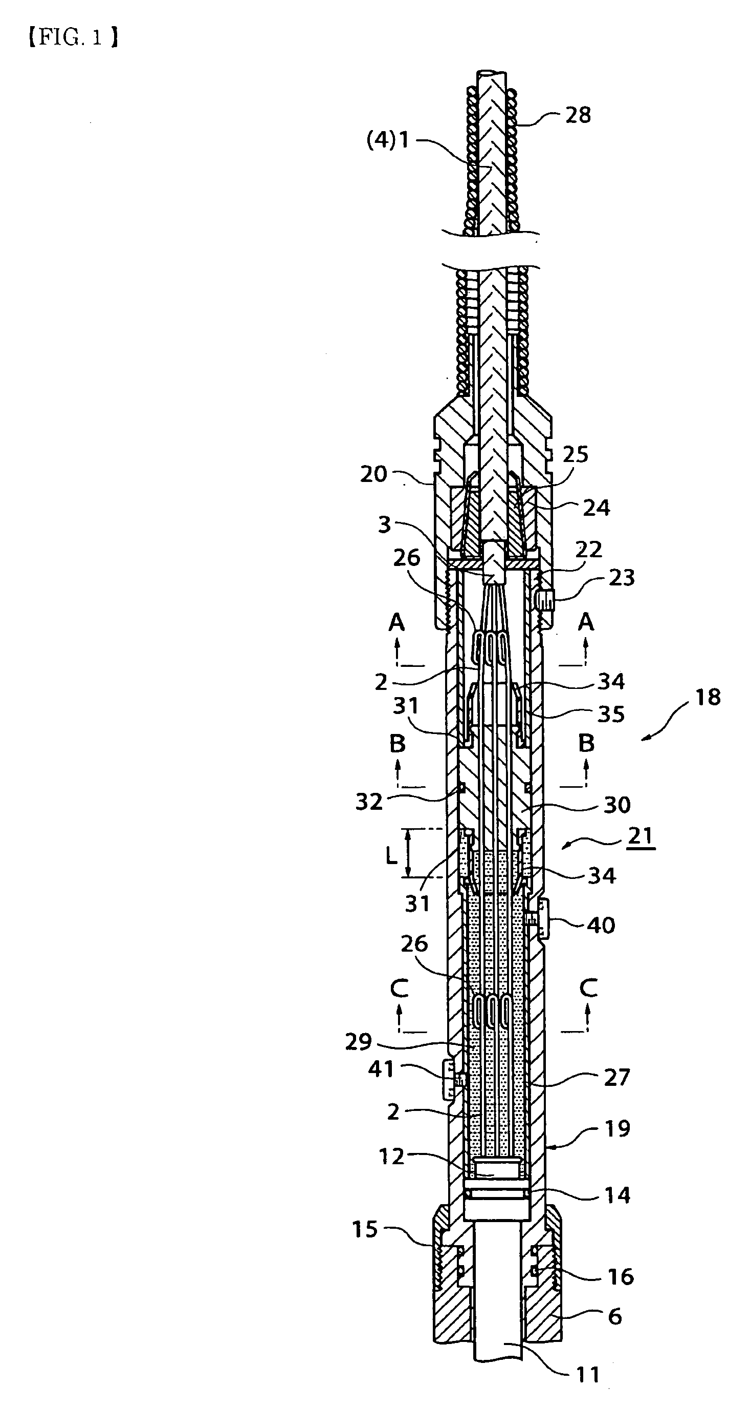
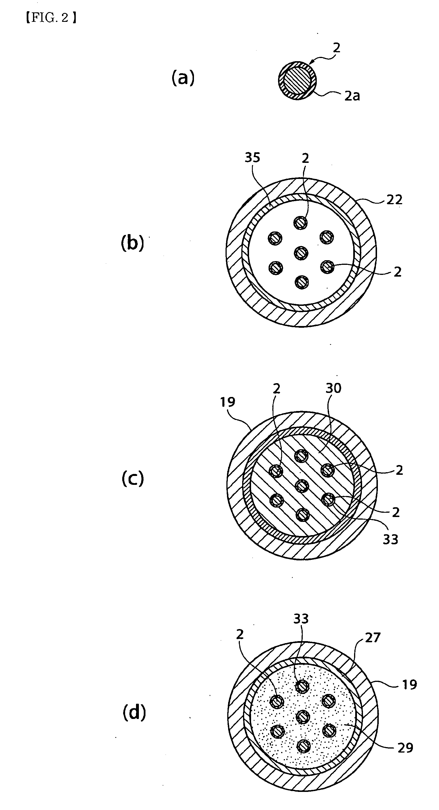
[0027]FIG. 1 is a longitudinal sectional view of a cable connection head according to an embodiment of the present invention, FIG. 2(a) is a sectional view of a sheathed cable, and FIGS. 2(b), (c), and (d) are sectional views along A-A, B-B, and C-C of FIG. 1. FIG. 3, FIG. 4, and FIG. 5 are enlarged views of FIG. 1 showing states where the movable sealing member is displaced up, to the middle, and down. FIG. 6 is a sectional view of the state with the cable connection head filled with an insulating oil. In the figures, the example is shown of filling an insulating oil in the state with the cable connection head vertically stood up.
[0028] The explanation will be made here referring to the drawings. Note that the explanation will be given assigning common notations to common components.
[0029] The cable connection head 18 is connected to various types of measuring devices (well logging sondes) designed to be lowered to a depth of several thousand meters below the surface along the borehole. It is provided with a bottom head body 19 connected to a top part of a measuring device body 6 and a top head body 20 connected to the bottom head body 19. The top and bottom head bodies 19 and 20 are connected at the mating connection part 22 and fixed by a set screw 23 so as to form inside the head body 21 a closed space housing the sheathed cables 2 led out from the sheathed cable 3 of the well logging cable 1.

Problems solved by technology

Among these, the part introducing the sheathed cables of the well logging cable to the head body is the most important and difficult part.
If borehole water enters the closed space, it reaches the metal part (terminal section 13) of the connector 11 and becomes a cause of poor insulation of the core conductor connection part and corrosion of the metal connection part.
The borehole fluid passes through these channels to reach the core conductors inside the sheathed cables 2 and the metal part of the connector 11 and cause poor insulation or corrosion.
However, when using a conventional cable connection head and conducting measurement for a long period (three months or more), frequently data could no longer be measured after about two months.
When investigating the cause, it was found that the borehole water reached the metal part of the connector (core conductor connection part) and caused poor insulation and corrosion of the metal connection part.

Method used


Image

  • Structure for a cable connection head
  • Structure for a cable connection head
  • Structure for a cable connection head

Examples


embodiments

[0046] (1) Test Well A, set depth 483 m (borehole temperature: 120° C.) [0047] Set period: Aug. 23, 2001 to Sep. 11, 2002 (385 days) [0048] (2) Test Well B, set depth 1,790.7 m (borehole temperature: 135° C.) [0049] Set period: Oct. 28, 2003 to Jan. 28, 2004 (92 days)

[0050] As a result of the tests of (1) and (2), it was possible to confirm that even if a large pressure is applied to the movable sealing member from the top side, the movable sealing member can move in a piston-like manner, so entry of borehole fluid at the movable sealing member can be prevented and smooth continuous measurement is possible.


PUM


Abstract

[PROBLEM] To fill a cable connection head with an insulating oil and provide a movable lid member of the oil to ensure a long-term insulating property in the cable connection head and enable long-term continuous use of a measuring device. [MEANS FOR SOLUTION] A cable connection head 18 having a head body 21 comprised of a bottom head body 19 and a top head body 20 connected to a measuring device body 6, having a well logging cable 1 passed through the top head body 30, and having core conductors of sheathed cables 2 connected to a connector 11 fit into the bottom head body 19, wherein the bottom head body 19 is filled with a low viscosity insulating oil 29 with a specific gravity heavier than the borehole fluid, outflow of the low viscosity insulating oil 29 is prevented, and a movable sealing member 30 preventing entry of borehole fluid is provided movably inside the bottom head body 19.

Description

TECHNICAL FIELD [0001] The present invention relates to a high temperature use cable connection head connecting a well logging cable and a measuring device when lowering various types of measuring devices into an oil well, geothermal well, or other well. PRIOR ART [0002] In an oil well or geothermal well, physical properties of the underground layer such as the temperature, pressure, seismic wave speed, and earthquakes and other vibration are measured by temperature and pressure well logging, electrical well logging, acoustic well logging, or the like and output characteristics by flow rate well logging etc. are measured using measuring devices in many cases. When making these measurements, various measuring devices (well logging sondes) are connected to cables and lowered into the borehole and the temperature, pressure, earthquake, and other measurement data measured at an underground depth are sent by signals to the ground through cables. In this case, a cable connection head is u...

Claims


Application Information

Patent Timeline
IPC IPC(8): E21B17/02H01R4/70E21B47/00E21B47/01H02G15/02H02G15/10
CPCE21B17/023E21B17/028E21B17/0285
Inventor TEZUKA, KAZUHIKOOHSAKI, YUTAKA
Owner JAPAN PETROLEUM EXPLORATION CO LTD
Learn More