
Method for displaying information responsive to sensing a physical presence proximate to a computer input device

a technology of input device and physical presence, which is applied in the direction of mechanical control device, manual control with single control member, instruments, etc., can solve the problems of increasing both the amount of power consumed and the cost of input device, and the number of transducers and switches that can be added to input device, so as to improve the “user experience” and reduce the clutter of display

Inactive Publication Date: 2005-12-15
MICROSOFT TECH LICENSING LLC
View PDF27 Cites 114 Cited by
  • Summary
  • Abstract
  • Description
  • Claims
  • Application Information

AI Technical Summary

Benefits of technology

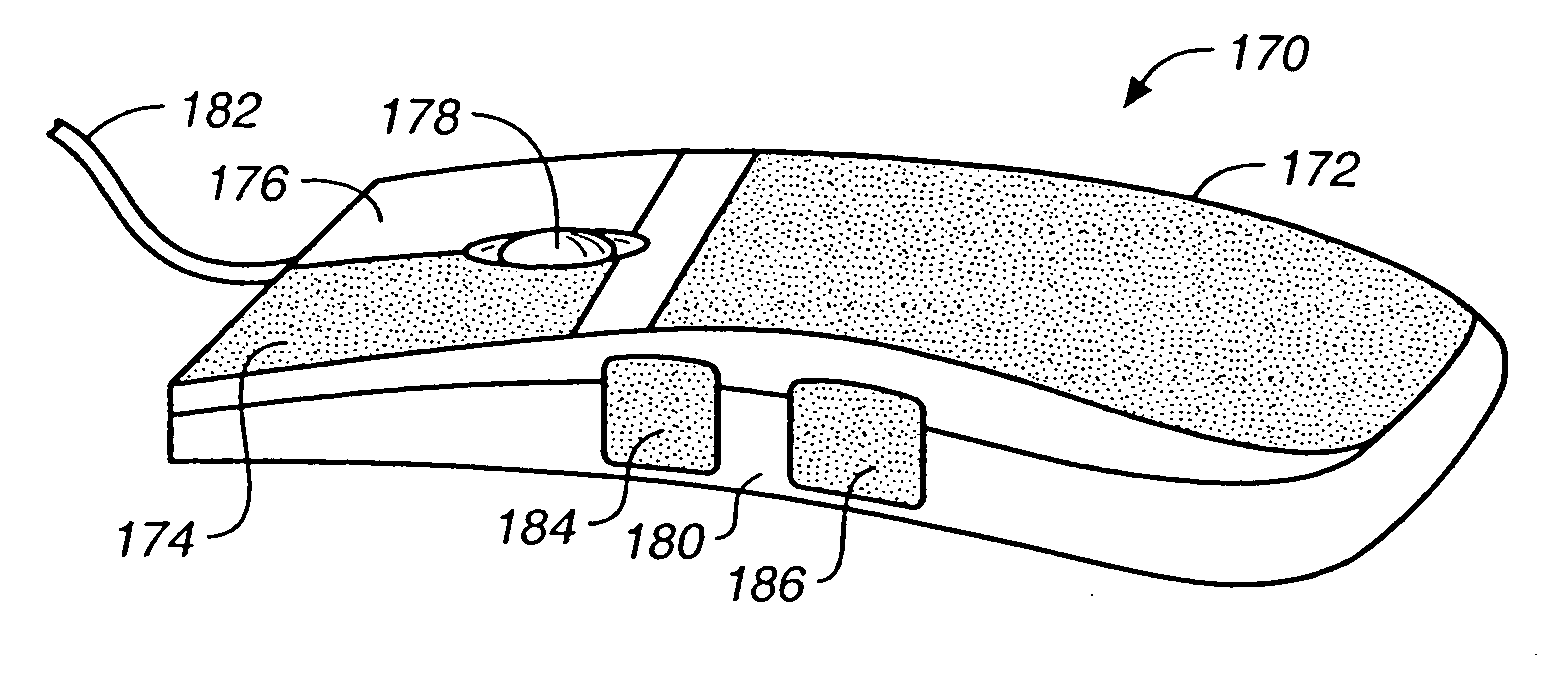
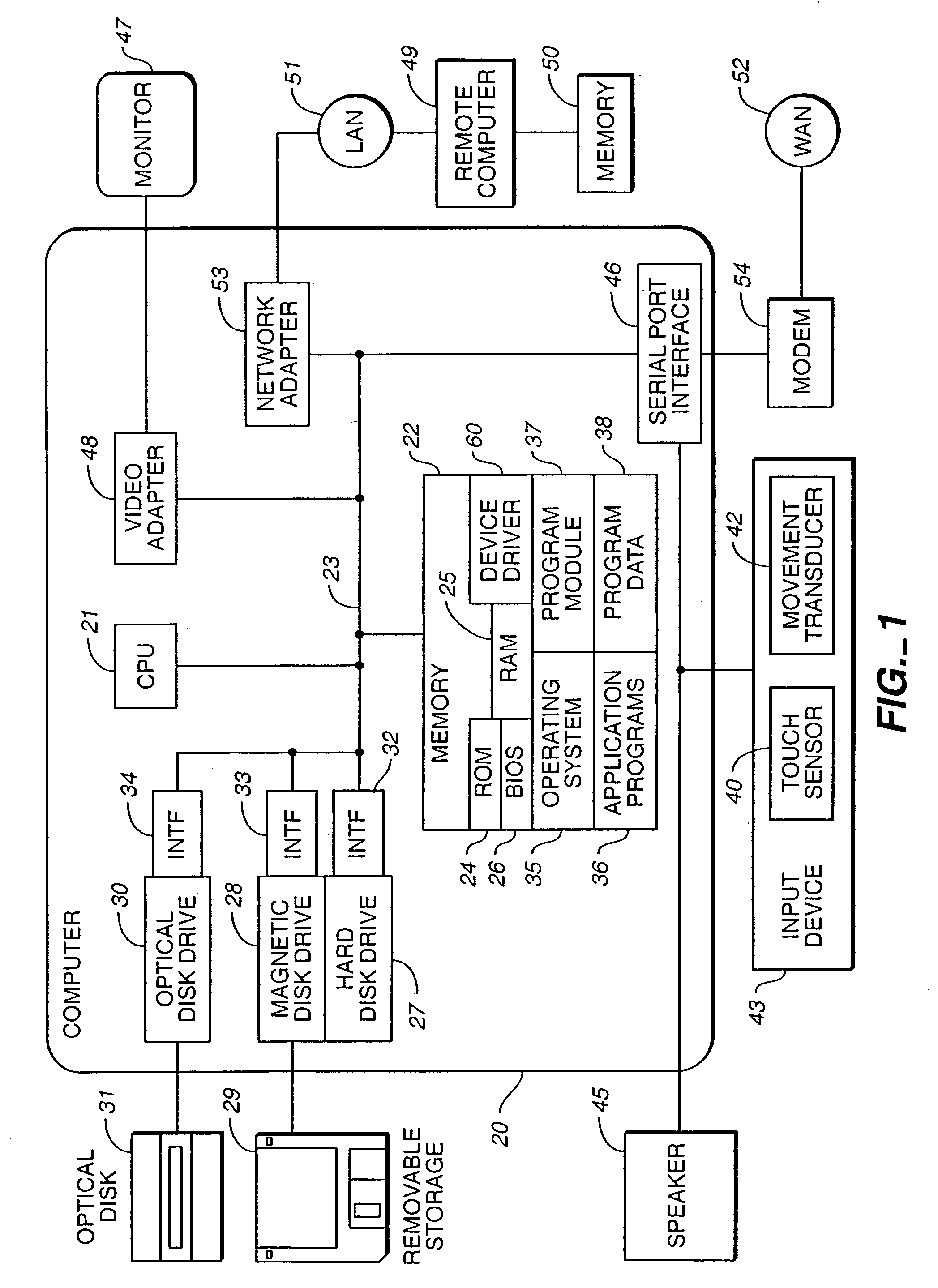
[0013] In an aspect of the present invention, keys, buttons, knobs, rocker switches or other auxiliary controls of an input device such as a keyboard, touchpad, trackball, game controller, monitor, joystick, steering wheel, headset or mouse can be augmented with sensors that detect contact or extreme proximity of a user's hand. According to another aspect, a sensed signal of the auxiliary control can provide the user with an on-screen display of status, state information, tool tips, help text or other feedback relevant to the control the user has touched without the user having activated (e.g., depress, turn, roll or otherwise activate) the control. Alternatively, acoustic or tactile feedback may be provided to the user instead of or in addition to the feedback provided by the on-screen display. Hence, a user can simply touch different buttons or other controls to explore their function assignment or status, or obtain other feedback. Such feedback can allow the user to better understand the consequences of their action, should he or she subsequently chooses to activate the control. Also, a user may quickly and casually be able to view status information.
[0019] In another aspect of the invention, toolbars, scrollbars and the like may only be displayed on a display screen in response to detection of a physical presence. Illustratively, touching, and not activating, an auxiliary control may cause on-screen display of a toolbar and breaking contact with the control may cause dismissing of the toolbar. In one aspect of the invention, a user may interface with the toolbar using an auxiliary control or input device as desired with one hand while continuing to touch the auxiliary control which caused the on-screen display of the toolbar. According to this aspect, display clutter can be reduced and available application screen area increased at appropriate times during program execution consistent with and governed by user action but without imposing any significant cognitive burden on the user to do so. This, in turn, is likely to significantly improve the “user experience”.

Problems solved by technology

Although it is desirable to increase the amount of information that an input device and its auxiliary controls can provide to the computer, the number of transducers and switches that can be added to an input device is limited by the user's ability to remember all of the functions that a particular transducer or switch performs and by the practicalities of the available or at least feasibly available real estate for the switches and transducers on the input device (e.g., keyboard or mouse).
The ability of a user to determine the functionality of each auxiliary control is also generally limited to a static label on or near the auxiliary control, activating each auxiliary control, clicking a button to select a menu option to request help file or reading a user manual.
However, association of LEDs or LCDs with each auxiliary control increases both the amount of power consumed and the cost of the input device.
Furthermore, LEDs and LCDs have very limited output forms and are separated from the main display (e.g., a computer monitor) causing the user to constantly have to look away from the screen and at the auxiliary control to determine the functionality or status of the control.
Such constant shifts of attention can mentally tire the user as he or she is forced to repetitively reacquire the current context.

Method used


Image

  • Method for displaying information responsive to sensing a physical presence proximate to a computer input device
  • Method for displaying information responsive to sensing a physical presence proximate to a computer input device
  • Method for displaying information responsive to sensing a physical presence proximate to a computer input device

Examples


Embodiment Construction

[0065] In accordance with illustrative embodiments of the present invention, an auxiliary control of an input device may be configured to detect when a physical presence (e.g., user's hand, stylus) touches the control so as to provide display and dismissal of a display widget on an “on demand” basis. The display widget may be a graphical user interface (GUI) and include information such as functionality (e.g., tool tips) and / or status information on an “on-demand” basis. An exemplary list of display widgets includes toolbars, tool glass sheet, scroll bars, window frames and window decorations, title bars, floating tool palettes, modal and non-modal dialog boxes, list or combo boxes, setting controls, buttons, text entry areas, etc.

[0066] A transition in a touch indication provided by the input device reflective of the user then making physical contact with an auxiliary control, such as by touching the control with a finger may cause a display widget to be displayed. A transition in...


PUM


Abstract

In a computer system, a touch sensitive input device having touch sensitive auxiliary controls system can be used to anticipate a user's action. When a user's hand approaches a touch sensitive input device, feedback can be displayed on a display screen. A user can receive feedback without activating the input device. The feedback may take the form of status information related to the feature controlled by the input device and can vary depending upon the application open. Likewise, when the hand of a user is moved away from the touch sensitive input device, the feedback brought on by sensing the user's hand may disappear.

Description

CROSS-REFERENCE TO RELATED APPLICATIONS [0001] This application is a divisional application of prior U.S. patent application Ser. No. 09 / 804,496, filed Mar. 13, 2001, which application is a continuation-in part of commonly assigned, copending U.S. patent application entitled “Proximity Sensor in a Computer Input Device” to Hinckley et al., filed Sep. 14, 1998 and assigned Ser. No. 09 / 152,434, now U.S. Pat. No. 6,456,275, issued Sep. 24, 2002, which is herein incorporated by reference. Also, prior U.S. patent application Ser. No. 09 / 804,496, filed Mar. 13, 2001 is a continuation-in part of commonly assigned, copending U.S. patent application entitled “A Technique For Implementing a Two-Handed Desktop Use Interface For a Computer” to Hinckley, filed Sep. 14, 1998 and assigned Ser. No. 09 / 152,432, now abandoned, which is herein incorporated by reference. Further, prior U.S. patent application Ser. No. 09 / 804,496, filed Mar. 13, 2001 is a continuation-in part of commonly assigned, copen...

Claims


Application Information

Patent Timeline
Patent Type & Authority Applications(United States)
IPC IPC(8): G06F3/02A63F13/06G05G9/047G06F3/01G06F3/023G06F3/033G06F3/038G09G5/00H01H7/08
CPCA63F13/06G06F2203/04805A63F2300/1043A63F2300/1068G05G9/047G05G2009/04766G05G2009/04774G06F3/0202G06F3/0219G06F3/033G06F3/03543G06F3/03547G06F3/03549G06F3/038G06F3/0481G06F3/04812G06F3/0482G06F3/0489G06F2203/04804A63F2300/1012A63F13/32A63F2300/1037A63F13/533A63F2300/308A63F13/33A63F13/24A63F13/214A63F13/285A63F13/212A63F2300/404
Inventor HINCKLEY, KENNETH P.BATHICHE, STEVEN N.VONG, WILLIAMCAUTHORN, JAMES H.LADAS, COREY M.FRY, KENNETH V.
Owner MICROSOFT TECH LICENSING LLC
Learn More