Compact multi-entrance-pupil imaging optical system

a multi-entrance pupil and optical system technology, applied in the field of compact multi-entrance pupil imaging optical system, can solve the problems of high cost and relatively low production yield of such components and systems, and achieve the effects of improving optical performance in terms of higher-order aberration, small physical length, volume and weigh

Active Publication Date: 2005-12-15
RAYTHEON CO
View PDF12 Cites 8 Cited by
  • Summary
  • Abstract
  • Description
  • Claims
  • Application Information

AI Technical Summary

Benefits of technology

[0005] The present approach provides a compact imaging optical system that achieves a large effective entrance pupil and image size, with a small physical length, volume, and weight. The optical light-gathering ability of the imaging optical system is equal to that of much longer imaging optical systems. The optical performance in terms of higher-order aberrations is improved as compared with larger imaging optical systems. The lenses and / or mirrors of the imaging optical system of the present approach are small in diameter and of low optical power in most cases, reducing their fabrication costs and the cost of the imaging optical system as compared with larger, higher-optical power lenses and / or mirrors. The present approach relates to imaging optical systems, as distinct from nonimaging optical systems.

Problems solved by technology

The production yield of such components and systems is typically relatively low, and costs are therefore higher, when using the higher-optical-power lenses and / or mirrors to achieve a compact imaging optical system.

Method used


Image

  • Compact multi-entrance-pupil imaging optical system
  • Compact multi-entrance-pupil imaging optical system
  • Compact multi-entrance-pupil imaging optical system

Examples


Embodiment Construction

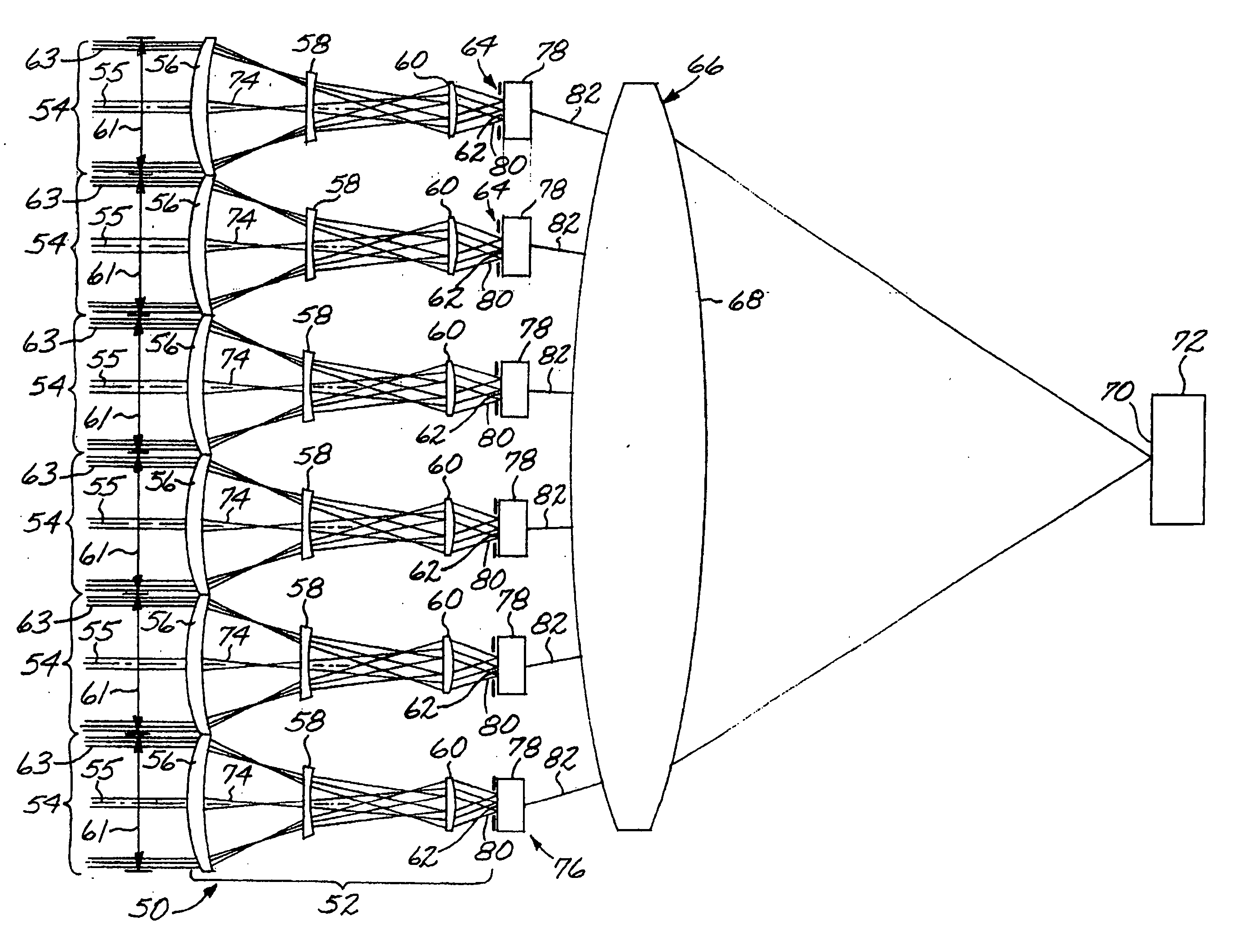
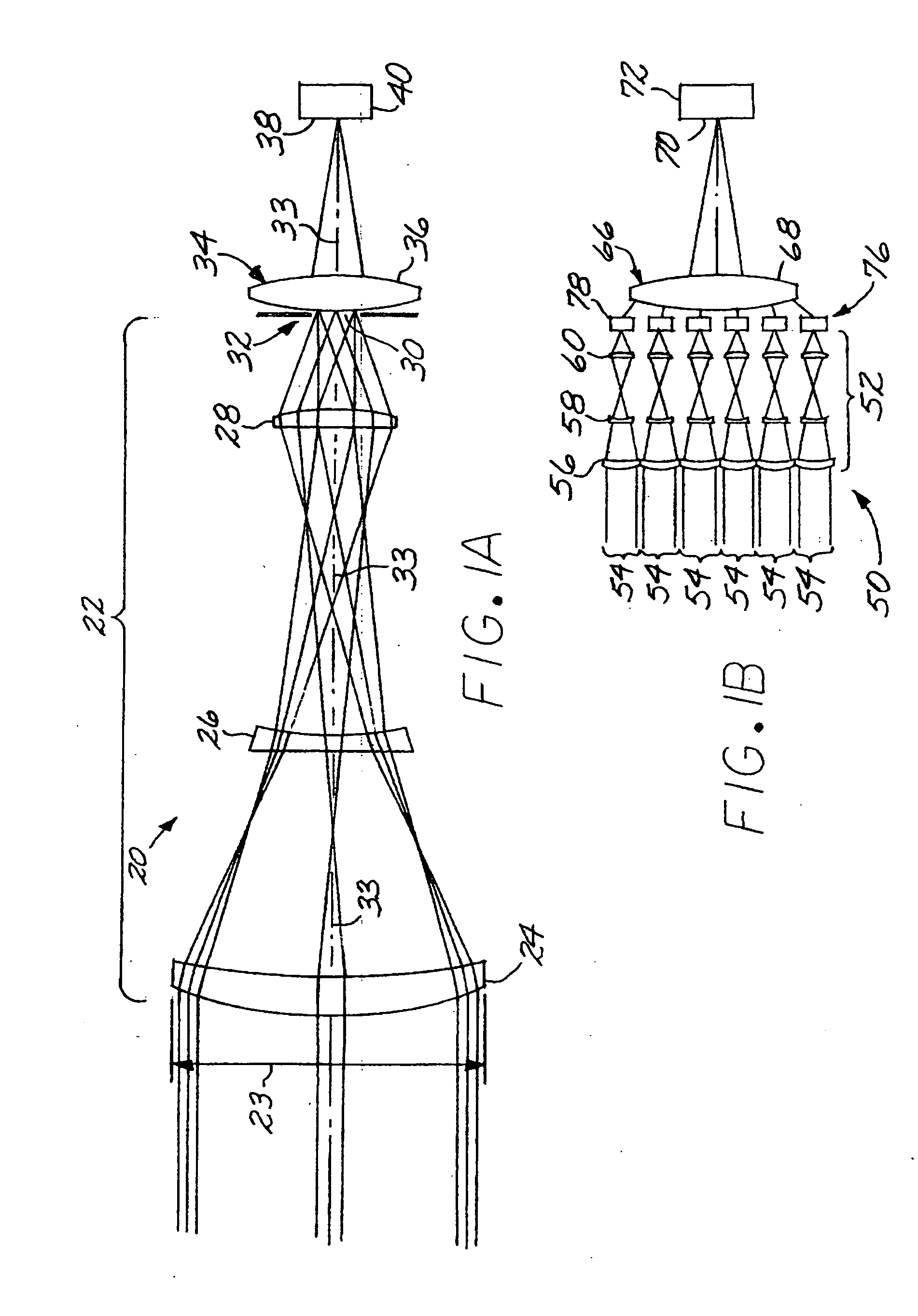
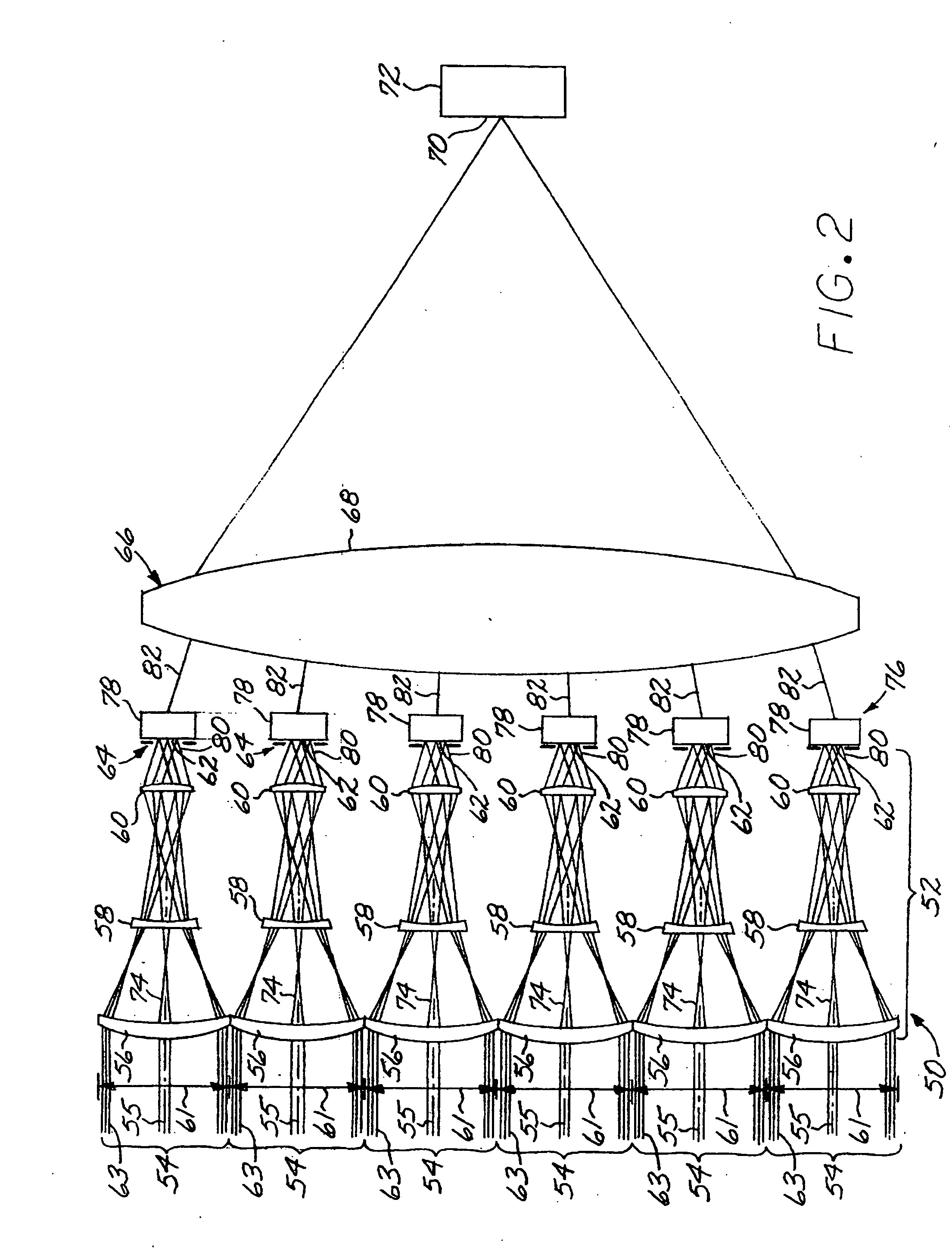
[0017]FIGS. 1A and 1B show the structures of, and a size comparison between, a single-entrance-pupil monolithic telescope in an imaging optical system (FIG. 1A) and a multi-entrance-pupil subtelescope array in an imaging optical system (FIG. 1B). FIG. 1A depicts, for comparison with the approach of the present invention, a single-entrance-pupil, monolithic imaging optical system 20 having a single-entrance-pupil, monolithic telescope 22 with a single entrance pupil 23, in this case a refractive telescope including three optically powered lenses 24, 26, and 28. An exit pupil 30 is at an exit aperture 32 of the single-entrance-pupil telescope 22. The light energy passing through the exit pupil 30 is imaged by an imager 34, represented by a lens 36, to a focal surface 38. There is a sensor 40, in this case a focal plane array sensor, at the focal surface 38. In this single-entrance-pupil telescope 22, all light that reaches the sensor 40 travels on a single optical path 33 through the ...


PUM


Abstract

An imaging optical system includes a subtelescope array, with at least two subtelescopes, each having a single entrance pupil and an exit light beam. Each subtelescope has an optical pointing axis, and the pointing axes for the subtelescopes are parallel. An imager forms an image from the exit light beams at an image surface, where there is a sensor such as a focal plane array. Preferably, a phase shifter array includes a phase shifter for each of the subtelescopes. The phase shifter array receives the exit light beam of each of the subtelescopes and has a capability to adjust the phase of at least one of the exit light beams. The imager receives the phase-shifted exit light beams.

Description

[0001] This invention relates to a light-imaging optical system and, more particularly, to a compact imaging system utilizing a multi-telescope array. BACKGROUND OF THE INVENTION [0002] In a typical telescope, a number of lenses and / or mirrors are arranged along a light path to gather and focus light rays onto an image surface. The image size and character may be described in part in terms of an entrance pupil (sometimes termed “pupil” herein) at the entrance aperture, the telescope magnification, and the imager behind the telescope to focus the light. The optical components are enclosed in a package structure that supports and aligns the optical components, and protects them from damage. One goal of the design of many imaging optical systems is to obtain satisfactory optical performance in as small a volume, in as short a physical length, and with as low a total weight, as possible. The physical length of the package is particularly important for many applications, which can have t...

Claims


Application Information

Patent Timeline
Patent Type & Authority Applications(United States)
IPC IPC(8): G02B23/00G02B23/04G02B23/06G02B27/00G02B27/09
CPCG02B23/04G02B27/0905G02B27/0087G02B23/06
Inventor CHEN, CHUNGTE W.ANDERSON, J. STEVE
Owner RAYTHEON CO
Why Eureka
Try Eureka