Low inductance, ferrite sub-gap substrate structure for surface film magnetic recording heads

a surface film, low inductance technology, applied in the field of magnetic recording heads, can solve the problems of low inductance, amplitude modulation problems, inability to provide a separate read head, etc., to reduce the overall volume of the ferrite core, reduce the resistance of the back gap, and increase the efficiency of the head

Inactive Publication Date: 2005-12-15
DUGAS MATTHEW P
View PDF10 Cites 10 Cited by
  • Summary
  • Abstract
  • Description
  • Claims
  • Application Information

AI Technical Summary

Benefits of technology

[0022] At this point, a back-bar is attached to the head member. The back-bar is formed from an appropriate magnetically permeable material, such as ferrite. The back-bar is provided with a structure so that it may be wrapped with an appropriate winding to produce a coil. The back-bar can be formed in a wide variety of configurations. In the simplest form, a single winding is provided around all of the back-bars, and when driven, will engage each of the channels simultaneously. Alternatively, a separate winding is provided for each channel, thus allowing each channel to be separately driven and controlled. Furthermore, any intermediary combination is allowable. That is, any particular combination of channels can be tied together. When the channels are timed and driven independently, sections of the magnetically permeable thin film must be removed between the channels. This prevents magnetic flux from passing from one channel to another through the thin film layer. It is the prevention of this cross talk which allows the multi-channel head to have its channels driven independently in time or phase. To produce such isolation, sections of the thin film can be removed by ion milling, wet chemical etching, or by any other known process. Other techniques such as selective plating or selective spattering could also be used.
[0023] In one embodiment, the present recording head provides a magnetically impermeable barrier between each channel so that actuation of one channel will in no way interfere with any other channel in the head. Hence, a significant portion of the magnetic volume of the head laying between each channel has been replaced with a ceramic material. Furthermore, in the back-gap area a back-bar has been incorporated. Utilization of the back-bar serves to reduce the reluctance of the back-gap and increase the efficiency of the head. Due to the reduction in overall volume of the ferrite core in the interchannel area, the head has a lower total inductance and is therefore more easily driven. Due to the lower inductance per channel, the frequency response of the head can be greatly increased. This increased response time translates into faster current rise times for the output flux signal generated. This ultimately leads to sharper written transitions when the head is used to apply servo patterns to magnetic media. It also allows for specific patterns to be accurately and quickly written by individually controlling and driving the various channels of the head.
[0024] In another aspect of the present invention, the magnetically permeable thin film layer is optimally configured to complete a magnetic circuit for each channel, while limiting mechanical interference of the film with the air bleed slots. Consideration must be given to the minimal requirements for completing the circuit and the engagement of the media against a head having a non-planar surface while minimizing the complexity of providing the air bleed slots. In addition, when working with components of this scale, consideration must be given to the etching or milling technique utilized to impart and define the thin film layer so that mechanical shear or peeling of the film is not induced by the tape's motion.
[0025] It is an object of the present invention to provide a multi-channel magnetic surface film servo write head having a reduced volume of magnetically permeable material.
[0026] It is a further object of the present invention to reduce the reluctance of the back-gap portion of the magnetic recording head.

Problems solved by technology

It is generally not feasible to provide a separate read head for each data track, therefore, the read head(s) must move across the width of the tape (in a translating direction), and center themselves over individual data tracks.
The trend toward thinner and thinner magnetic tape layers causes amplitude modulation problems with this and other amplitude based heads.
Such a head has very low inductance, however, it is extremely difficult to manufacture.
To date, pure thin film heads are generally not utilized for time based servo heads and are not seen as a practical way to produce such a magnetic head.
Hence, there is a large amount of unnecessary ferrite inductance.
In other words, as a result of the relatively large amount of extraneous ferrite, an unnecessarily high amount of inductance is created.
This requires greater write current from the drive circuitry, lowers the frequency response of the head, and increases the rise time of the writing pulses from the head.
Ultimately, this forms a barrier which hampers the magnetic flux; in other words the reluctance through the back-gap is relatively high and again, the head must be driven harder to compensate.
This is only really problematic in heads having a larger back-gap with respect to the writing gap, such as in Albrecht et al.
Techniques used to reduce the reluctance of video recording heads are not applicable to sub-gap driven heads.
Such problems are intensified with heads having multiple writing gaps, or channels.
In other words, excess and unused ferrite material is provided in between the channels which unnecessarily increases the overall inductance of the head.

Method used


Image

  • Low inductance, ferrite sub-gap substrate structure for surface film magnetic recording heads
  • Low inductance, ferrite sub-gap substrate structure for surface film magnetic recording heads
  • Low inductance, ferrite sub-gap substrate structure for surface film magnetic recording heads

Examples


Embodiment Construction

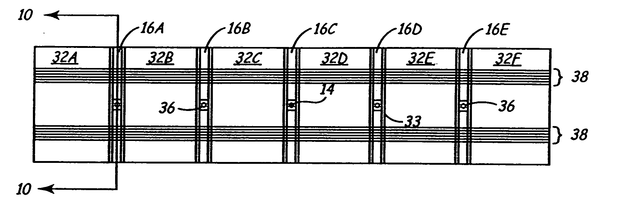
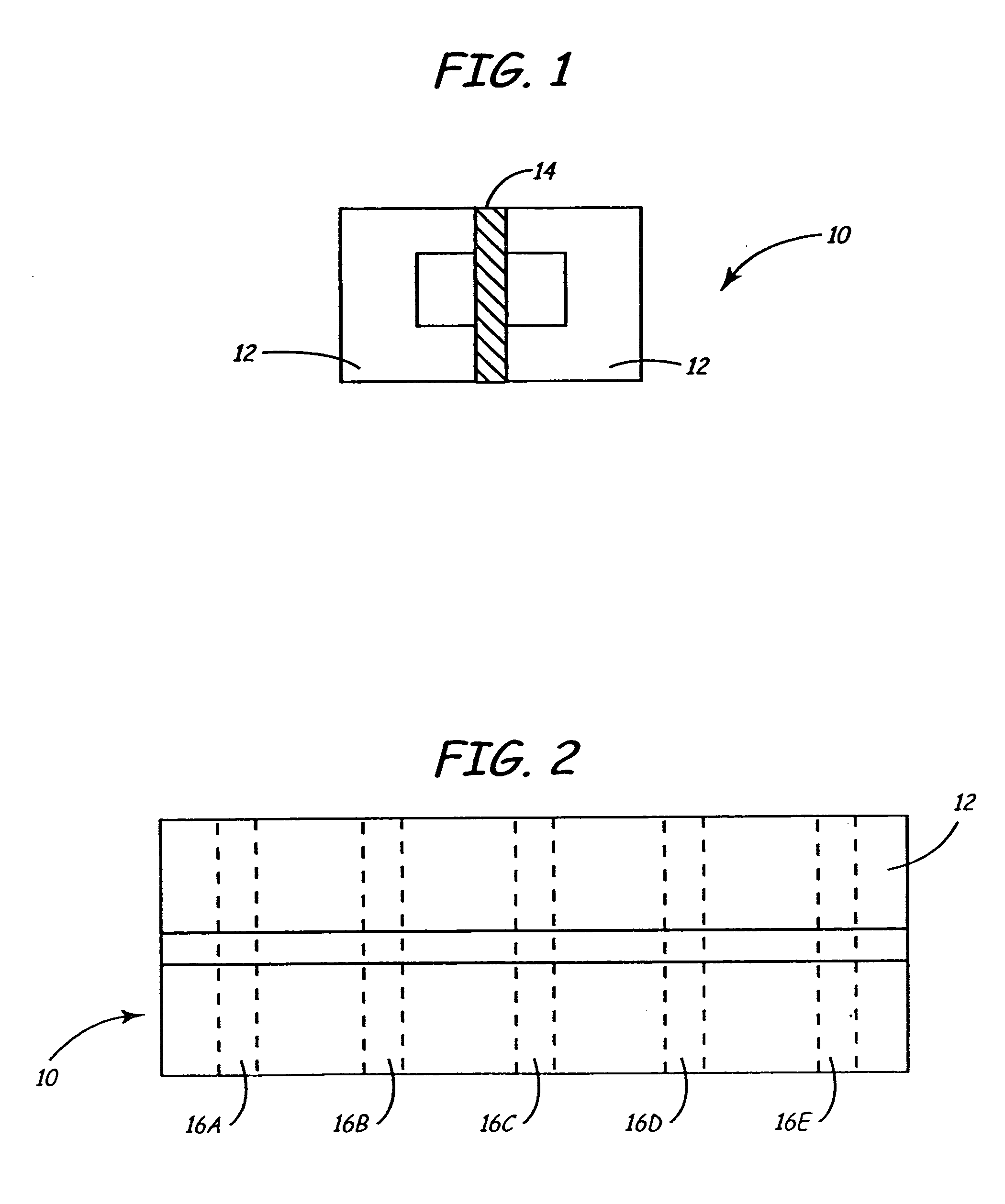
[0048] The present invention is a multi-channel head and method of making the same. Referring to FIG. 1, a substrate 10 is created by glass bonding two C-shaped ferrite blocks 12 to a medially disposed ceramic member 14. The sizes, shapes and relative proportions of the ferrite blocks 12 and ceramic member 14 may vary as dictated by the desired parameters of the completed recording head. Furthermore, the choice of materials may also vary so long as blocks 12 remain magnetically permeable while member 14 remains substantially magnetically impermeable. FIG. 2 is a top view of the substrate 10.

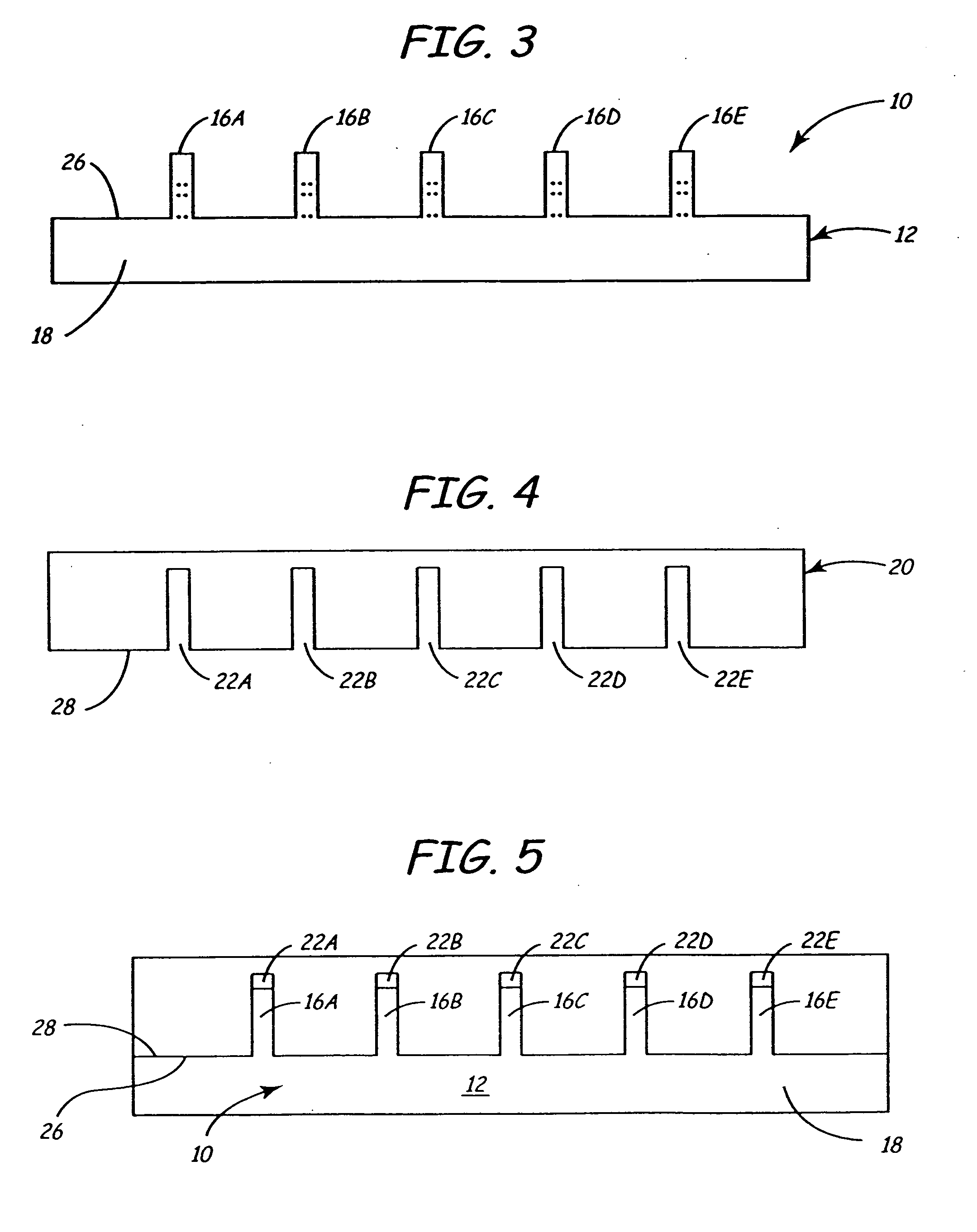
[0049] Referring to FIG. 3, substrate 10 is diced so as to form a plurality of columns 16A-16E which remain adhered to base 18. Columns 16A-16E are also shown by the dashed lines in FIG. 2, which illustrates how each column will have a ceramic portion (sub-gap) bonded between two ferrite poles. The dashed lines are merely illustrative of future columns, as the substrate 10 in FIG. 2 has yet to b...


PUM

PropertyMeasurementUnit
inductancesaaaaaaaaaa
permeableaaaaaaaaaa

Abstract

A thin film magnetic recording head is fabricated by forming a substrate from opposing ferrite blocks which have a ceramic member bonded between them. This structure is then diced to form a plurality of columns, wherein each column has a ferrite / ceramic combination. Each column represents a single channel in the completed head. A block of ceramic is then cut to match the columned structure and the two are bonded together. The bonded structure is then cut or ground until a head is formed, having ceramic disposed between each channel. A ferrite back-gap is then added to each channel, minimizing the reluctance of the flux path. The thin film is patterned on the head to optimize various channel configurations.

Description

[0001] This application is a continuation of application Ser. No. 09 / 475,420, filed on Dec. 30, 1999, which is hereby incorporated in its entirety by reference.FIELD IF THE INVENTION [0002] This invention relates generally to magnetic recording heads and more particularly to a structure for a ferrite driven, surface thin-film magnetic recording head wherein a substantial portion of the ferrite core has been replaced with a magnetically impermeable material and an optimal back-bar arrangement which reduces the inductance and increases the efficiency of the head. BACKGROUND OF THE INVENTION [0003] While a variety of data storage mediums are available, magnetic tape remains a preferred forum for economically storing large amounts of data. In order to facilitate the efficient use of this media, magnetic tape will have a plurality of data tracks extending in a transducing direction of the tape. Once data is recorded onto the tape, one or more data read heads will read the data from those...

Claims


Application Information

Patent Timeline
Patent Type & Authority Applications(United States)
IPC IPC(8): G11B5/65G11B5/127G11B5/193G11B5/29G11B5/31G11B5/48G11B5/584G11B5/596
CPCG11B5/127G11B5/232Y10T29/49055G11B20/1211G11B5/3116G11B5/4893G11B20/1217G11B5/235G11B5/193G11B5/584G11B5/1276Y10T29/49057G11B5/29G11B5/295G11B5/23
Inventor DUGAS, MATTHEW P.
Owner DUGAS MATTHEW P
Why Eureka
Try Eureka