Optical apparatus

a technology of optical equipment and optics, applied in the field of optical equipment, can solve the problems of reducing the snap-shooting ability of the optical equipment, reducing the initial velocity calculation error, and long time to obtain, and achieve the effect of short time and increased accuracy

Inactive Publication Date: 2005-12-15
CANON KK
View PDF10 Cites 48 Cited by
  • Summary
  • Abstract
  • Description
  • Claims
  • Application Information

AI Technical Summary

Benefits of technology

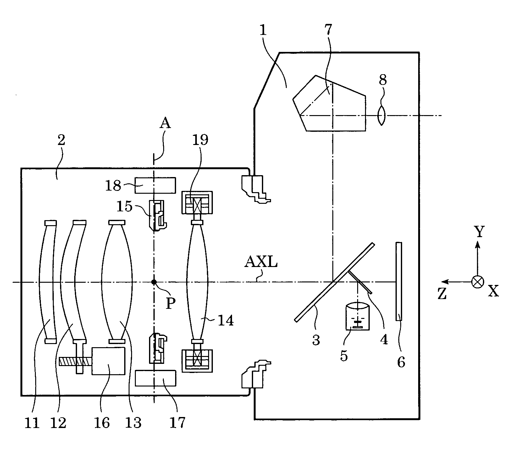
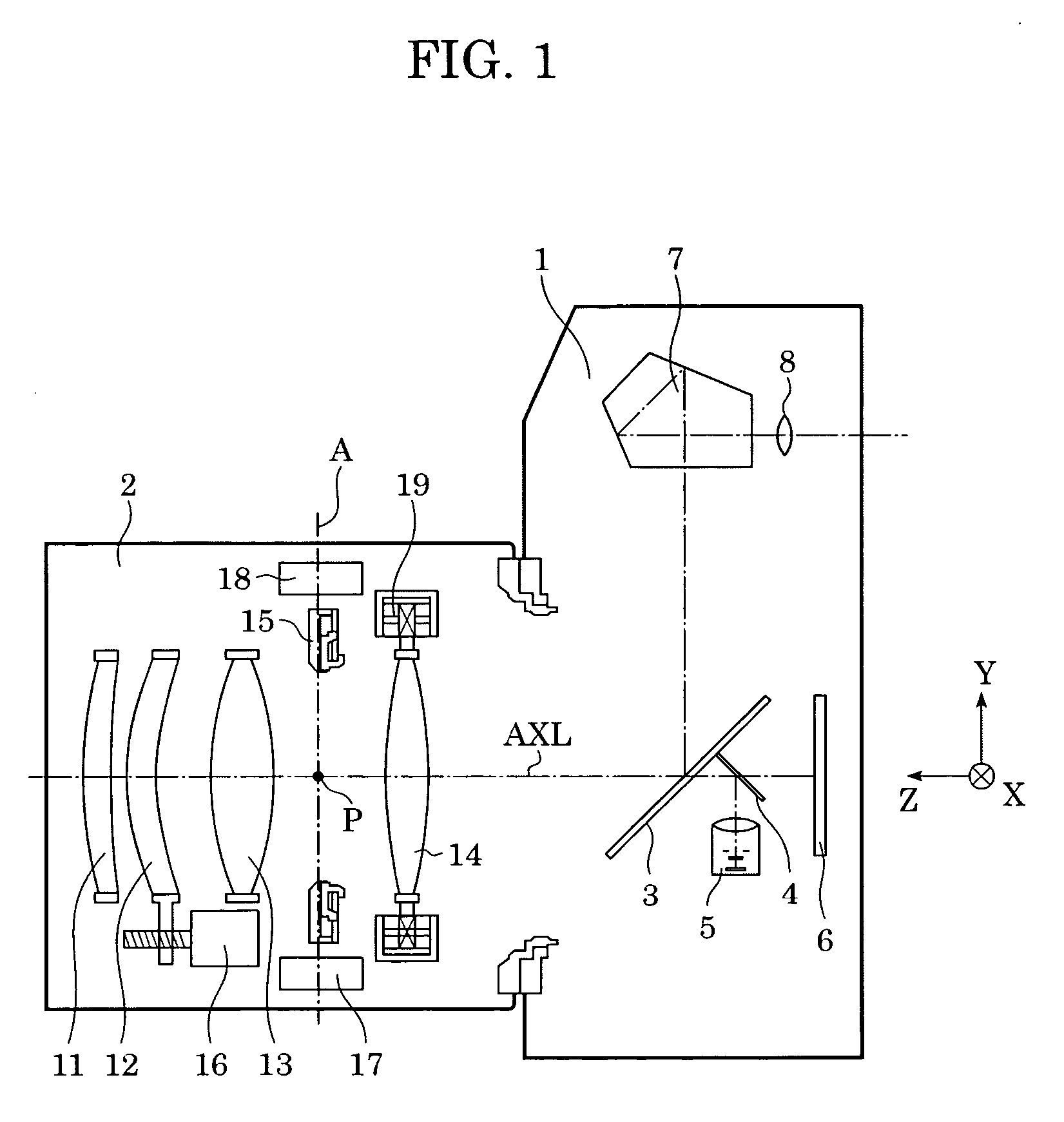
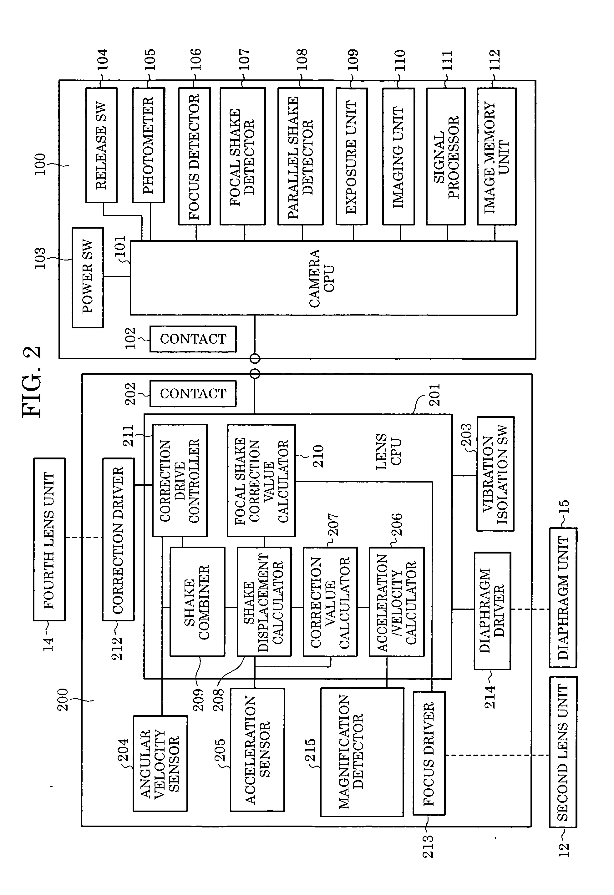
[0016] At least one exemplary embodiment provides an optical apparatus which can be applied to a signal lens reflex camera and which performs image shake correction with increased accuracy in a short time.

Problems solved by technology

Therefore, it requires a long time to obtain the shake displacement, which reduces the snap-shooting ability of shooting apparatuses.
However, the actual camera shake is not periodic, and therefore the calculated initial velocity includes a large error.
However, when this method is applied to a single lens reflex camera, although high correction accuracy can be obtained, the camera shake cannot be detected during exposure.

Method used


Image

  • Optical apparatus
  • Optical apparatus
  • Optical apparatus

Examples


Embodiment Construction

[0025] The following description of at least one exemplary embodiment is merely illustrative in nature and is in no way intended to limit the invention, its application, or uses.

[0026] Processes, techniques, apparatus, and materials as known by one of ordinary skill in the art may not be discussed in detail but are intended to be part of the enabling description where appropriate. For example optical photographic systems are discussed and any material that can be used to form elements of optical photographic systems should fall within the scope of exemplary embodiments (e.g. glass, Si). Additionally the actual size of the elements of optical photographic systems or other elements of exemplary embodiments may not be discussed, however any size from macro to micro and nano are intended to lie within the scope of exemplary embodiments (e.g. lenses with diameters of nanometer size, micro size, centimeter, and meter sizes). Additionally exemplary embodiments are not limited to visual op...


PUM


Abstract

An optical apparatus is provided which uses image shake information generated by a shake correction unit to improve an image by reducing the amount of image shake.

Description

BACKGROUND OF THE INVENTION [0001] 1. Field of the Invention [0002] The present invention generally relates to an optical apparatus and in particular but not exclusively an optical apparatus having a function of improving image shake. [0003] 2. Description of the Related Art [0004] Many optical apparatuses, (e.g., cameras and interchangeable lenses), have vibration isolation systems for reducing image shake caused by hand motion or the like. [0005] Hand motion is normally a vibration with a frequency of about 1 to 10 Hz. In an optical apparatus having a typical vibration isolation system for taking a picture without blurring even when hand motion occurs during exposure, vibration of the optical apparatus is detected. Then, a correcting lens is moved along a plane perpendicular to an optical axis in accordance with the detection result (optical vibration isolation), or an area to be extracted (output) from a shot image is shifted in accordance with the detection result (electronic vi...

Claims


Application Information

Patent Timeline
Patent Type & Authority Applications(United States)
IPC IPC(8): G02B7/10G02B27/64G03B5/00G03B17/00H04N5/232
CPCG02B7/102G02B27/646G03B5/00H04N5/23287G03B2217/005H04N5/23248H04N5/23258G03B2205/0007H04N23/68H04N23/6812H04N23/687
Inventor ISHIKAWA, MASANORISUGITA, JUNSHINOHARA, MITSURUNAGAO, YUKI
Owner CANON KK
Why Eureka
Try Eureka