Fuel vapor adsorption filters

a technology of adsorption filter and fuel vapor, which is applied in the direction of machine/engine, combustion air/fuel air treatment, separation process, etc., can solve the problems of increasing manufacturing costs and potential leakage of fuel vapor through the edge, and achieve the effect of improving fuel vapor adsorption performance and reducing cos

Active Publication Date: 2005-12-22
TOYOTA BOSHOKU KK
View PDF11 Cites 27 Cited by
  • Summary
  • Abstract
  • Description
  • Claims
  • Application Information

AI Technical Summary

Benefits of technology

[0008] It is accordingly an object of the present invention to teach fuel vapor adsorption filters that have improved fuel vapor adsorption performance and that can be manufactured at a relatively reduced cost.
[0010] Since the frame is formed by heat-pressing the peripheral edge portion(s) of the first non-woven fabric(s), it is possible to position the fuel vapor adsorption agent more proximally to the frame in comparison with a known frame that is molded by an injection molding process. Therefore, a peripheral region of the filter body within the frame where there is no fuel vapor adsorption agent may be reduced or minimized. As a result, the amount of fuel vapor that may potentially leak through such a peripheral region of the filter body can be minimized, improving the fuel vapor adsorption performance of the filter.
[0011] In addition, it is not necessary to use an additional material for forming the frame. Therefore, the manufacturing cost of the filter can be reduced.
[0013] In another embodiment, the filter further includes at least one resin net for covering the filter body. The at least one resin net has a peripheral edge that is heat-pressed together with the peripheral edge portion of the first non-woven fabrics in order to form the frame. Since the peripheral portion of the resin net is additionally used to form the frame, the strength of the frame can be improved.
[0015] Since the holding layer and the at least one cover layer are at least partly bonded or joined to each other through a bonding or joining means, it is possible to prevent the cover layer from being peeled off or otherwise removed from the holding layer. Therefore, it is possible to prevent the adsorption agent, such as activated carbon granules, from being worn or broken by the flapping or movement of the cover layer.

Problems solved by technology

However, this may result in the potential leakage of fuel vapor through the edge portion 92f.
This may result in a problem of increased manufacturing costs.

Method used


Image

  • Fuel vapor adsorption filters
  • Fuel vapor adsorption filters
  • Fuel vapor adsorption filters

Examples


first representative embodiment

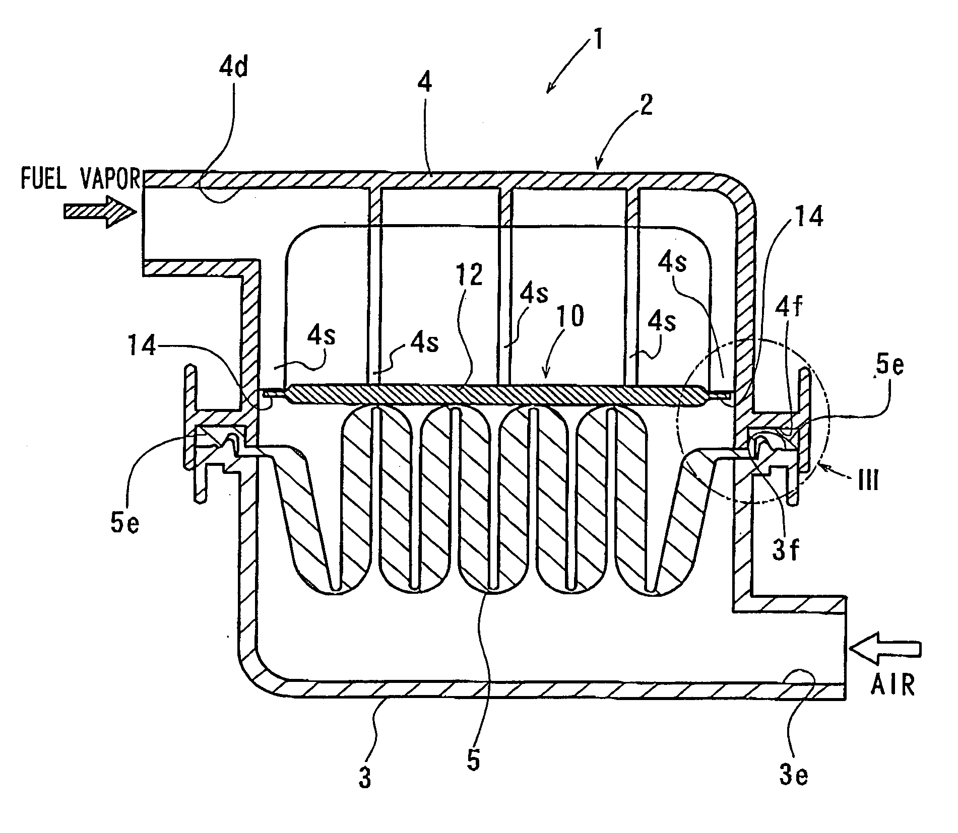
[0031] A first representative embodiment of the present invention will now be described with reference to FIGS. 1 to 5. Referring to FIG. 4, an air cleaner 1 is shown that includes a fuel vapor adsorption filter 10.

[0032] The air cleaner 1 has a housing 2 that is molded from a synthetic resin. The housing 2 includes a lower housing 3 and an upper housing 4 that respectively have an inlet port 3e and an outlet port 4d. The upper side of the lower housing 3 and the lower side of the upper housing 4 are open. An air cleaner element 5 has an outer peripheral frame 5e that is clamped between an open edge 3f of the lower housing 3 and an open edge 4f of the upper housing 4 as shown in FIG. 3. With this arrangement, the air cleaner element 5 is fixed in position so as to extend across the space within the housing 2 in order to filter intake air that is supplied to an engine (not shown).

[0033] The fuel vapor adsorption filter 10 is mounted within the housing 2 and is disposed on the downs...

second representative embodiment

[0047] A second representative embodiment will now be described in connection with FIGS. 6 to 9. This representative embodiment is a modification of the first representative embodiment. Therefore, like members are given the same reference numerals as in the first representative embodiment and the description of these members may not be repeated.

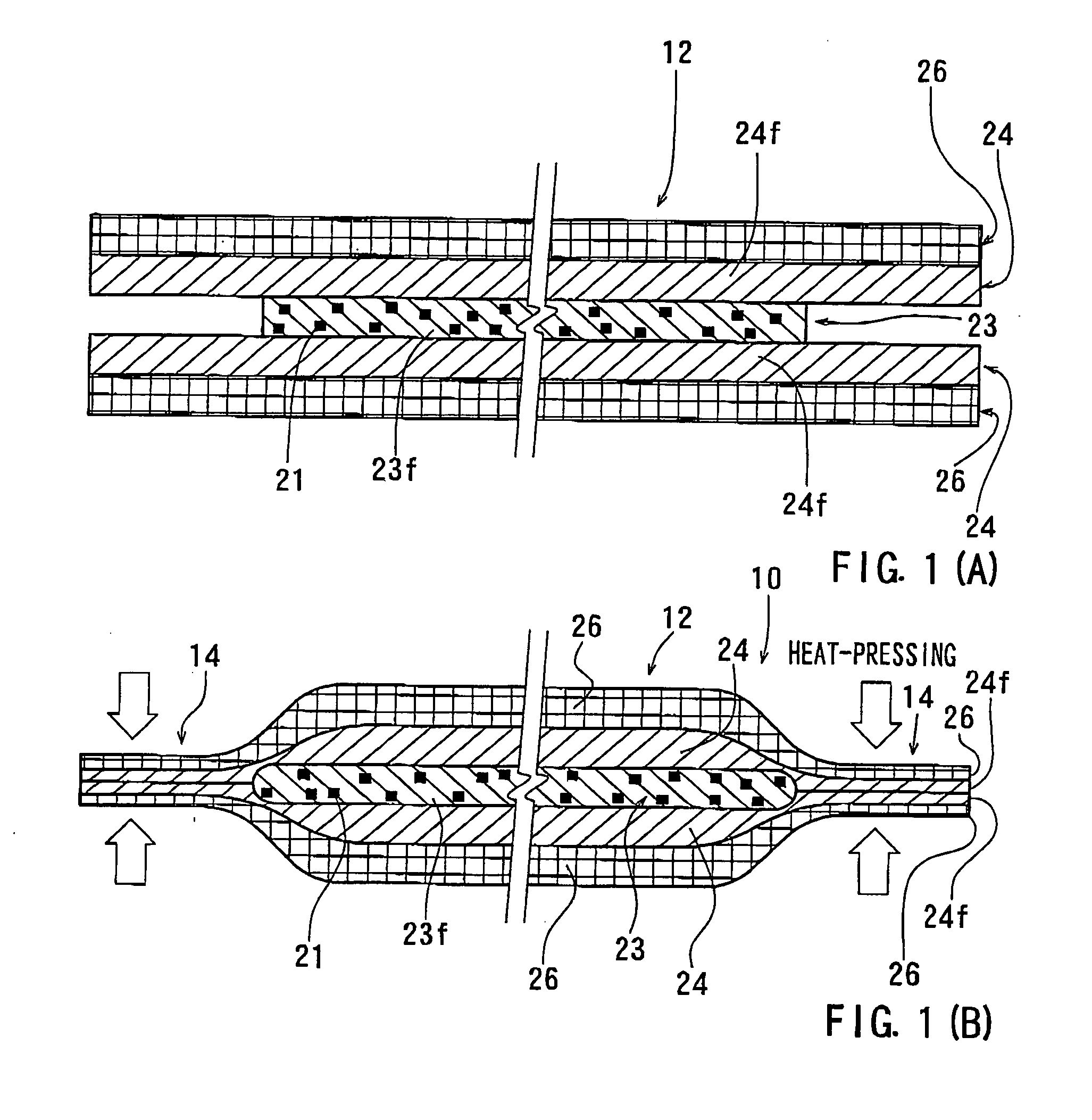
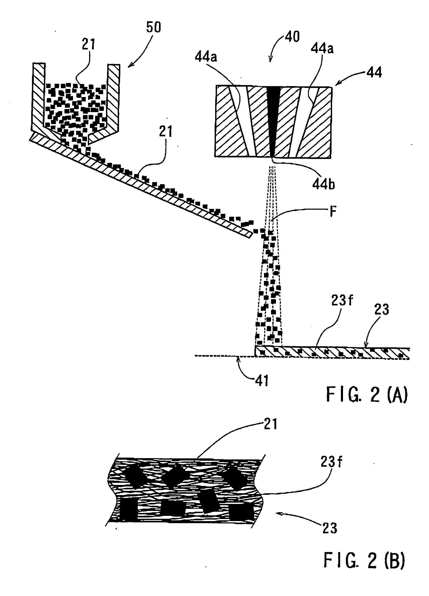
[0048] As described above, according to the first representative embodiment, the cover layers 24 of the fuel vapor adsorption filter 10 are formed by laying the formed resin fibers of the non-woven fabric 24f, which are formed by the non-woven fabric manufacturing apparatus that has the same construction as the non-woven fabric manufacturing apparatus 40, above and below the non-woven fabric 23f of the holding layer 23. Therefore, the resin fibers F of the holding layer 23 and the resin fibers of the cover layers 24 may be naturally bonded to each other during the overlaying process. However, in case of relatively small boding forces between...


PUM

PropertyMeasurementUnit
thicknessaaaaaaaaaa
melting pointaaaaaaaaaa
diameteraaaaaaaaaa

Abstract

A fuel vapor adsorption filter includes a fuel vapor adsorption agent; a filter body containing the fuel vapor adsorption agent therein, and a frame formed to surround the filter body. The frame is adapted to be mounted within an intake air channel connected to an engine, so that the filter body is operable to adsorb a fuel vapor within the intake air channel when the engine has been stopped. Non-woven fabrics form the filter body. The non-woven fabrics have peripheral edge portions. Heat-pressing the peripheral edge portions of the non-woven fabrics forms the frame.

Description

[0001] This application claims priority to Japanese patent application serial number 2004-182617, the contents of which are incorporated herein by reference. BACKGROUND OF THE INVENTION [0002] 1. Field of the Invention [0003] The present invention relates to fuel vapor adsorption filters, and in particular to fuel vapor adsorption filters that have a filter body and a frame surrounding the circumference of the filter body. The filter may be mounted within an intake air channel connected to an engine, e.g., an internal combustion engine, via the frame. The filter body may adsorb a fuel vapor within the intake air channel when the engine has stopped. [0004] 2. Description of the Related Art [0005] Japanese Laid-Open Patent Publication No. 2003-42017 teaches a known fuel vapor adsorption filter. As shown in FIGS. 10(A), 10(B), and 10(C), a fuel vapor adsorption filter of this publication has a filter body 92 and a frame 94 surrounding the filter body 92. During the operation of an engi...

Claims


Application Information

Patent Timeline
Patent Type & Authority Applications(United States)
IPC IPC(8): B01D53/02B01D53/04F02M25/08F02M35/02F02M35/024
CPCB01D53/0415B01D2253/102B01D2253/25B01D2257/702F02M35/024B01D2258/012B01D2259/4516F02M25/0854F02M35/02B01D2257/708Y10S55/05
Inventor HIRATA, RYU
Owner TOYOTA BOSHOKU KK
Why Eureka
Try Eureka