
Earthquarke prediction method and system thereof

a prediction method and system technology, applied in wave based measurement systems, instruments, reradiation, etc., can solve the problems of high difficulty in realizing such a system, large number, etc., and achieve the effect of low equipment cost and low equipment cos

Inactive Publication Date: 2005-12-22
NEC MOBILING LTD
View PDF8 Cites 190 Cited by
  • Summary
  • Abstract
  • Description
  • Claims
  • Application Information

AI Technical Summary

Benefits of technology

"The present invention provides an earthquake prediction method and system that can accurately predict seismic events with low cost and without the need for installation of measurement equipment at a multiplicity of points. The method involves measuring magnetic fields at various points within an observation area and analyzing them to estimate telluric currents and the change patterns of these currents over time. By eliminating magnetic field noise and analyzing the data collected from mobile units, the system can accurately predict the seismofocal zone, seismic intensity, and time of occurrence of a seismic event. The system includes mobile units carrying magnetic force line sensors and GPS position detectors, and a data storage and analysis center. The system can also be used in existing fixed structures or mobile units to collect observation data and predict seismic events."

Problems solved by technology

With the current financial difficulties faced by national and municipal governments, such an establishment of a large number of observation facilities would be a tremendous burden, and the costs for maintaining and operating the observation system would render the realization of such a system highly problematic.

Method used


Image

  • Earthquarke prediction method and system thereof
  • Earthquarke prediction method and system thereof
  • Earthquarke prediction method and system thereof

Examples


Embodiment Construction

[0031] Explanation next regards the present invention with reference to the accompanying figures.

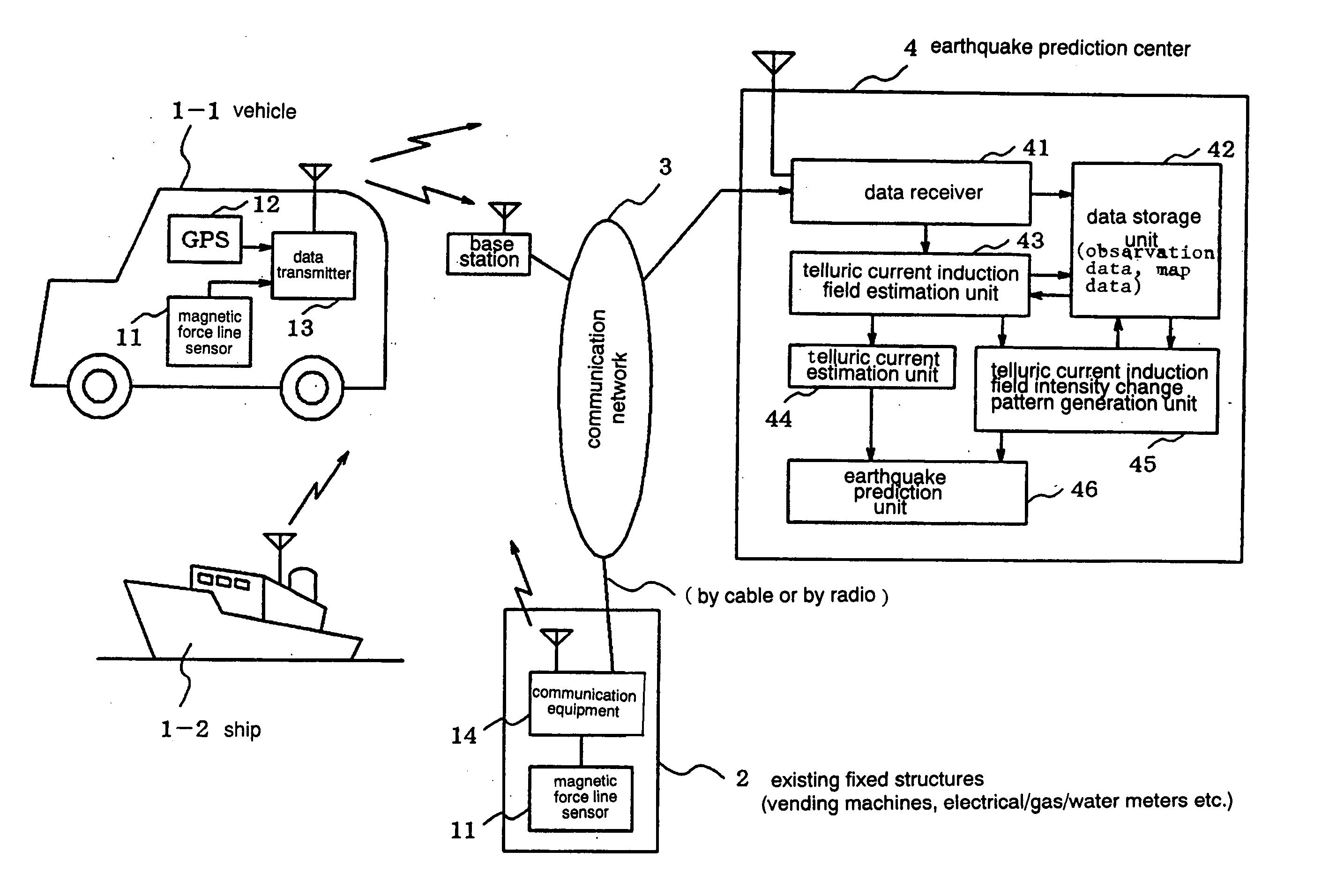
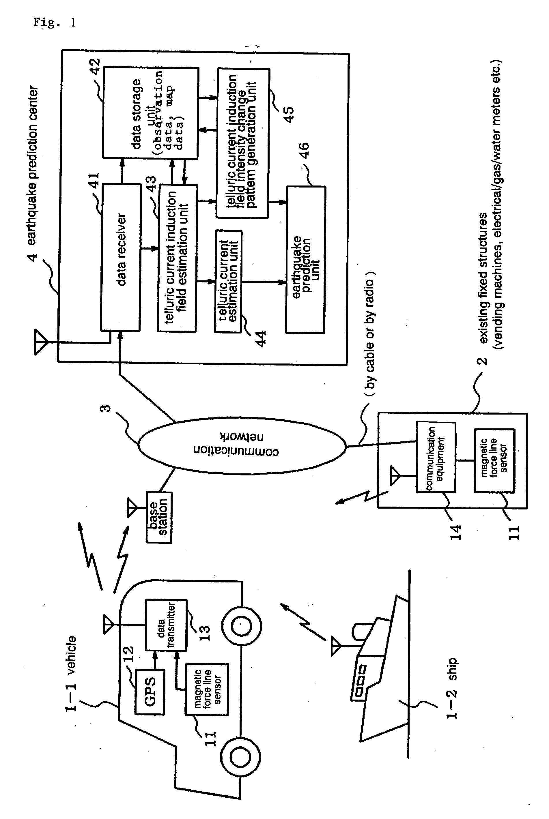
[0032]FIG. 1 is a block diagram showing an embodiment of the present invention, and shows an earthquake prediction system that uses: mobile units 1 such as a vehicle or a ship that are capable of movement on land or on sea; or existing fixed structures 2 that have been selected in advance within the observation area, to collect observation data at a multiplicity of points within the observation area and predict, for example, the seismofocal zone and time of occurrence of an earthquake.

[0033] In this case, the earthquake prediction system is provided with: mobile unit 1 in which, for example, magnetic force line sensor 11 and GPS position detector 12 are mounted and which transmits observation data to earthquake prediction center 4; existing fixed structure 2 in which magnetic force line sensor 11 and communication equipment 14 have been installed; communication network 3 for transmitti...


PUM


Abstract

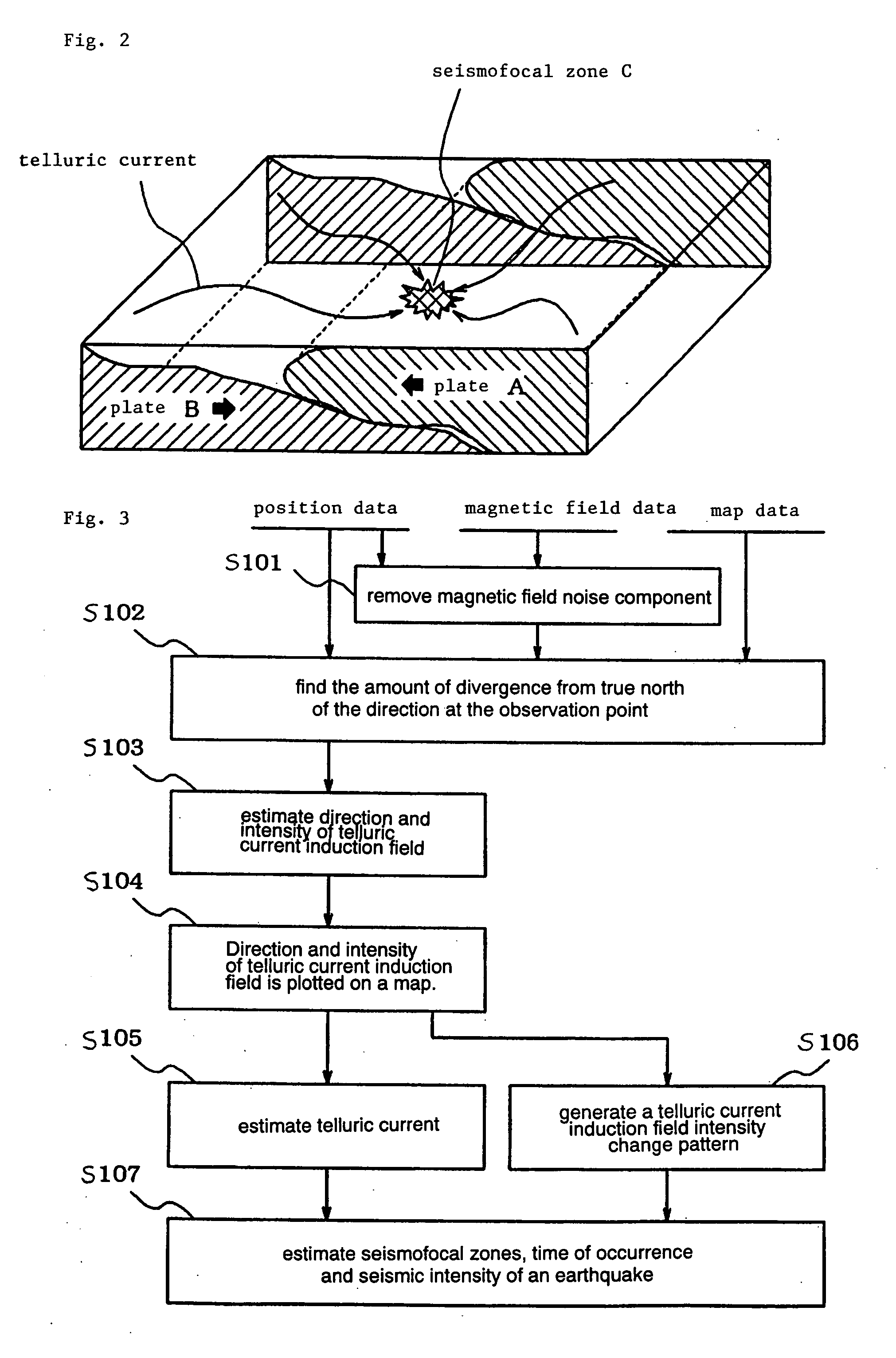
Vehicles (1-1) or ships (1-2) each carry a magnetic force line sensor (11), a GPS position detector (12), and a data transmitter (13) and travel within an observation area transmitting magnetic field data and position data of each point to an earthquake prediction center (4). A telluric current induction field estimation unit (43) of the earthquake prediction center (4) estimates telluric current induction fields based on the observation data that it receives and collects. A telluric current estimation unit (44) estimates telluric currents based on the results of estimating the telluric current induction fields. A telluric current induction field intensity change pattern generation unit (45) generates patterns that indicate the change over time of the intensity of telluric current induction fields. An earthquake prediction unit (46) analyzes the state of distribution of the telluric currents and the patterns of change in the intensities of the telluric current induction fields and estimates a seismofocal zone, seismic intensity, and time of occurrence of a seismic event.

Description

TECHNICAL FIELD [0001] The present invention relates to an earthquake prediction method and system, and more particularly to an earthquake prediction method and system for measuring the magnetic field of each point within an observation area to predict earthquakes. BACKGROUND ART [0002] The Japanese archipelago is situated on volcanic chains, and the occurrence of a massive earthquake disaster is therefore a major concern in the oceans to the east, southeast and south, not to mention throughout the archipelago. To protect the lives and property of citizens from earthquake disasters, more suitable measures must be taken not only for systems for recovery following an earthquake, but for earthquake prediction, and for this purpose, the establishment of a low-cost, and moreover, highly accurate and effective earthquake prediction technology is urgently required. [0003] From ancient times, many examples of precursors of impending earthquakes have been reported, such as the agitated behav...

Claims


Application Information

Patent Timeline
Patent Type & Authority Applications(United States)
IPC IPC(8): G01V1/00G01V3/00
CPCG01V1/008G01V1/01G01V1/00
Inventor YOMODA, TOMONARIYOSHIDA, TOSHIO
Owner NEC MOBILING LTD
Learn More