Low power PLL for PWM switching digital control power supply

a digital control power supply and low power technology, applied in the field of switching power supplies, can solve the problems of short pulse, large ripple, and requirement for a fairly high clock frequency

Active Publication Date: 2005-12-22
SILICON LAB INC
View PDF2 Cites 29 Cited by
  • Summary
  • Abstract
  • Description
  • Claims
  • Application Information

AI Technical Summary

Problems solved by technology

Large differences between input and output voltage levels will result in very short pulse width switching pulses that switch the transistors in the switching power supply relative to the overall period of the switching operation.
This can result in the requirement for a fairly high clock frequency that is output by a clock generator.
However, for a power supply that steps down from 75 volts to 3 volts or even 1 volt, this would result in a considerable amount of ripple.
The problem with such clocks is they tend to be complex, as they must be accurate clocks, and they also draw considerable power.

Method used


Image

  • Low power PLL for PWM switching digital control power supply
  • Low power PLL for PWM switching digital control power supply
  • Low power PLL for PWM switching digital control power supply

Examples


Embodiment Construction

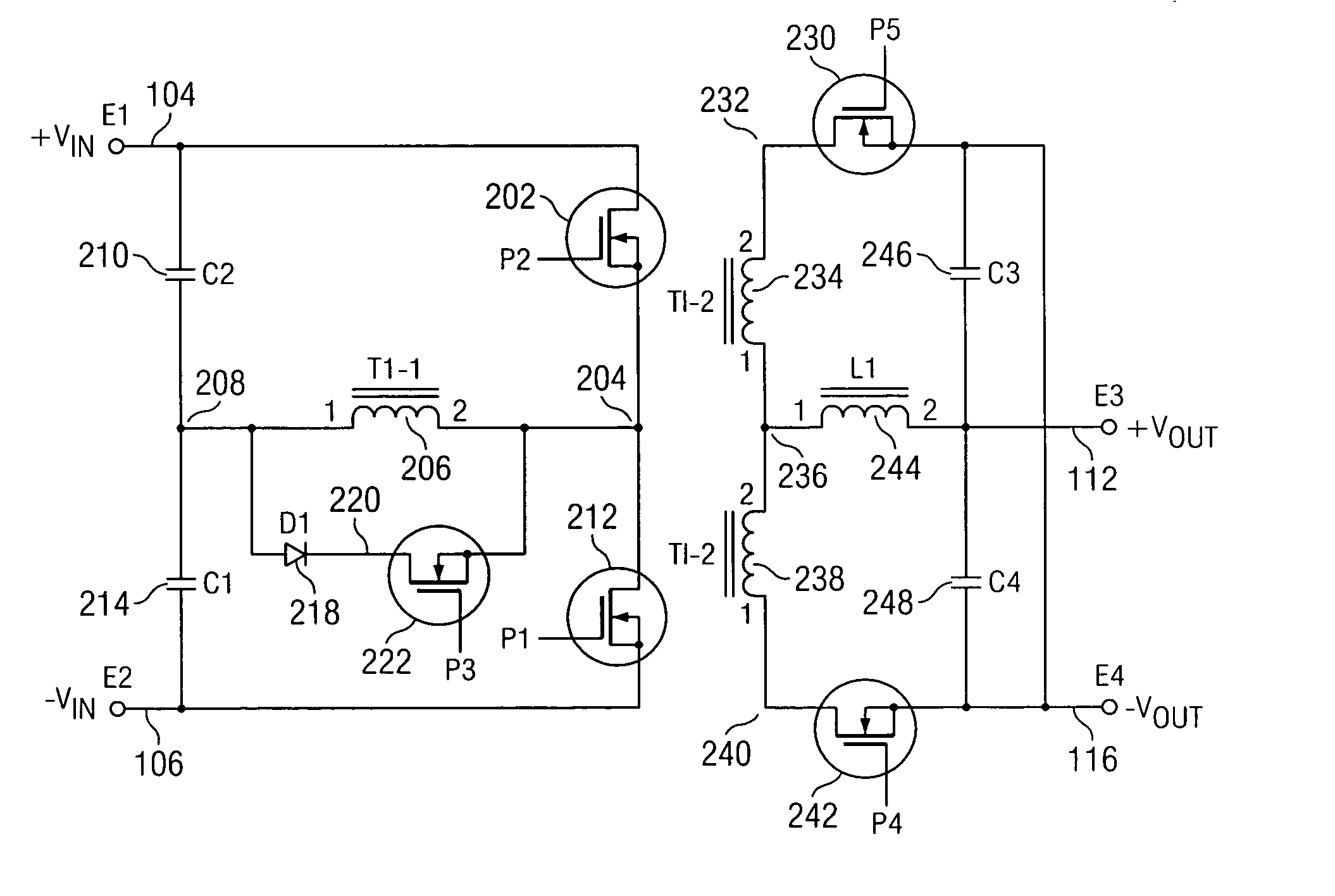
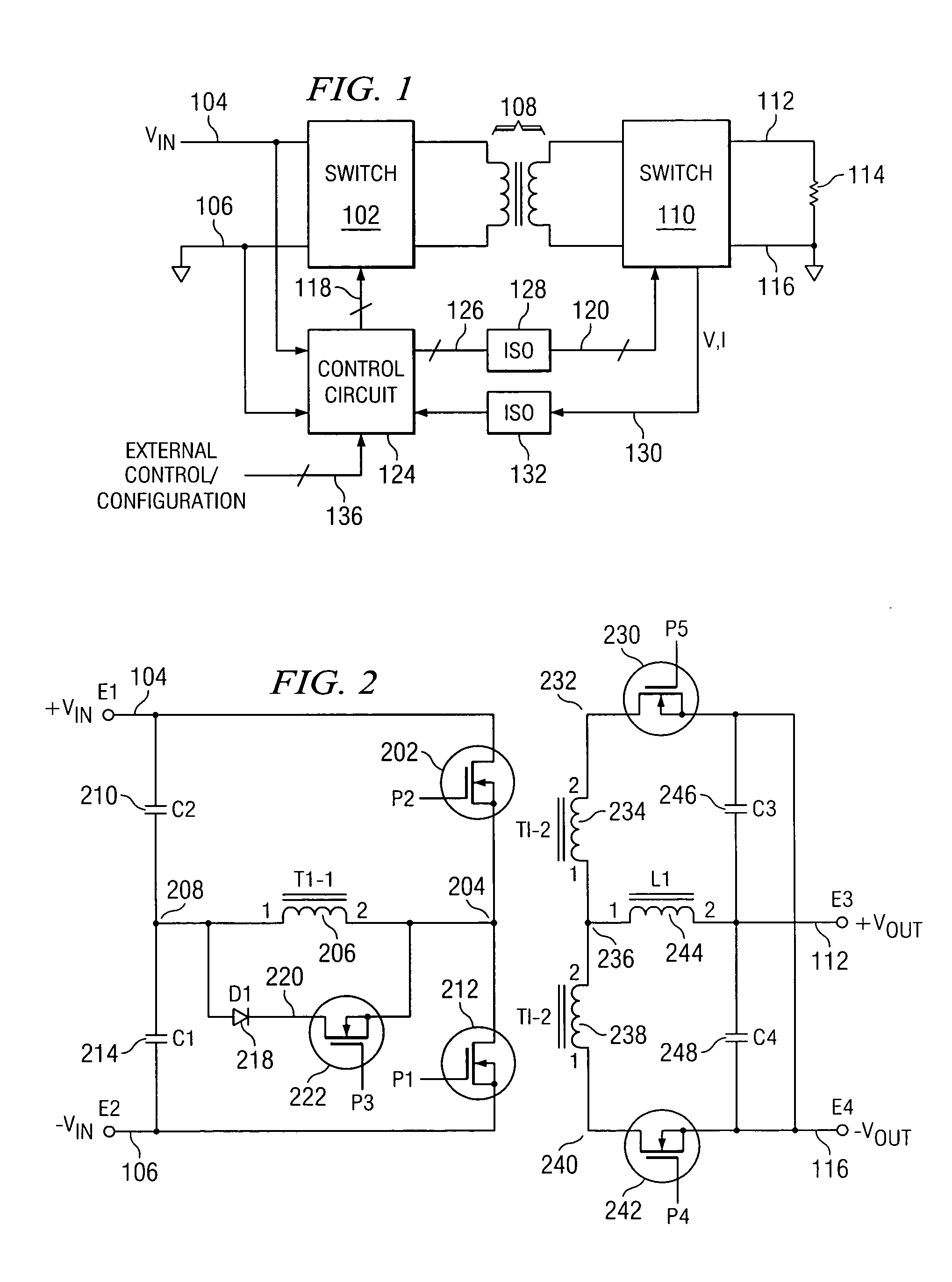
[0018] Referring now to FIG. 1, there is illustrated a top level schematic diagram for the switching power supply of the present embodiment. The main portion of the power supply comprises a primary switch group 102 that is operable to receive an input voltage on a node 104, this being a DC voltage, and ground on a node 106. The primary switch group 102 is coupled through an isolation transformer 108 to a secondary switch group 110. The secondary switch group 110 is operable to drive an output voltage node 112 that is connected to one terminal of a load 114, the secondary switch group 110 also having a ground connection on a node 116, the load 114 disposed between the node 112 and the node 116. The two switch groups 102 and 110 are operable to operate in conjunction with various pulse inputs on a control bus 118 associated with the primary switch group 102 and with various pulse inputs on a control bus 126 associated with the secondary switch group 110.

[0019] A digital control circu...


PUM


Abstract

A timing source for a pulse generator is disclosed, which timing source includes an input for receiving a reference clock output at a reference operating frequency. An edge generator is provided for generating a plurality of clock edges from an edge of the reference clock during one period thereof, with the spacing of the plurality of clock edges being a multiple of a predetermined divisor. As such, the resolution of such spacing emulates a higher clock frequency than the reference operating frequency. A selector then selects one of the plurality of clock edges from a reference one thereof to define the width of a pulse.

Description

CROSS-REFERENCE TO RELATED APPLICATIONS [0001] This application is related to pending U.S. patent application Ser. No. 10 / 742,509, filed Dec. 19, 2003, entitled “DIGITAL CONTROL CIRCUIT FOR SWITCHING POWER SUPPLY WITH PATTERN GENERATOR” (Atty. Dkt. CYGL-26,332), which is incorporated in its entirety herein by reference.TECHNICAL FIELD OF THE INVENTION [0002] The present invention pertains in general to switching power supplies and, more particularly, to the timing system for generating pulses that drive the switching elements in the power supply. BACKGROUND OF THE INVENTION [0003] Switching power supplies utilize a plurality of switches which are turned on and off to switch an input DC voltage at a first level across a transformer to a load, the output voltage disposed at a different and lower DC voltage level than the input DC voltage. For some power supply applications, the initial input DC voltage may be at a high level of, for example, 75 volts. This voltage then must be reduced...

Claims


Application Information

Patent Timeline
Patent Type & Authority Applications(United States)
IPC IPC(8): H02M3/335H03K3/017H03K5/00H03K5/13H03K7/08H03L7/099
CPCH02M3/33576H03K5/133H03K7/08H03L7/0996H03K2005/00156H03K2005/00202H03L7/0805H03K2005/00032
Inventor LEUNG, KA Y.LEUNG, KAFAI
Owner SILICON LAB INC
Why Eureka
Try Eureka