RFID system utilizing parametric reflective technology

a technology of parametric reflection and rfid, which is applied in the field of radio frequency identification (rfid) interrogators and data tags, can solve the problems of increasing manufacturing costs, significant manufacturing costs of each tag, and cost associated with the chip itself, so as to reduce the aggregate read time, reduce the manufacturing cost of the tag, and the interrogator and the tag range is wide.

Active Publication Date: 2005-12-22
VUBIQ
View PDF38 Cites 154 Cited by
  • Summary
  • Abstract
  • Description
  • Claims
  • Application Information

AI Technical Summary

Benefits of technology

[0008] What is needed is a chipless RFID system and method that would provide greater range between the interrogator and the tags, lower manufacturing costs of the tags, and less aggregate read time for multiple tags in proximity to each other. What is also needed is a system which accurately locates and tracks a tag.

Problems solved by technology

Considering that active and passive tags have electronic circuitry in the form of a chip, the manufacturing costs for each tag is significant.
Not only is there a cost associated with the chip itself, but there are also numerous processing steps required in order to place the chip onto the tag.
In addition, existing tags require a method of mechanically and electrically connecting the antenna to the chip, which adds to manufacturing costs.
If more than one tag is within range of the interrogator, multiple interfering transmissions can result from the interrogator attempting to read a single tag.
Also of note, in the types of RFID systems thus described, there are no straightforward methods to accurately locate and track a tag.

Method used


Image

  • RFID system utilizing parametric reflective technology
  • RFID system utilizing parametric reflective technology
  • RFID system utilizing parametric reflective technology

Examples


Embodiment Construction

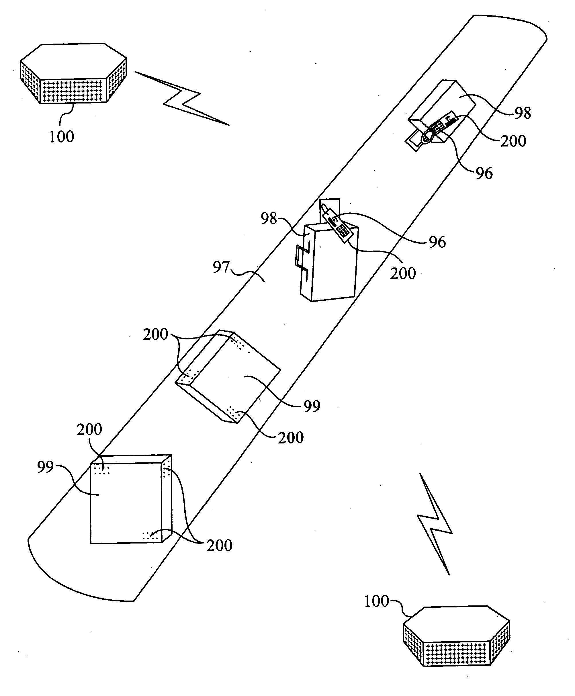
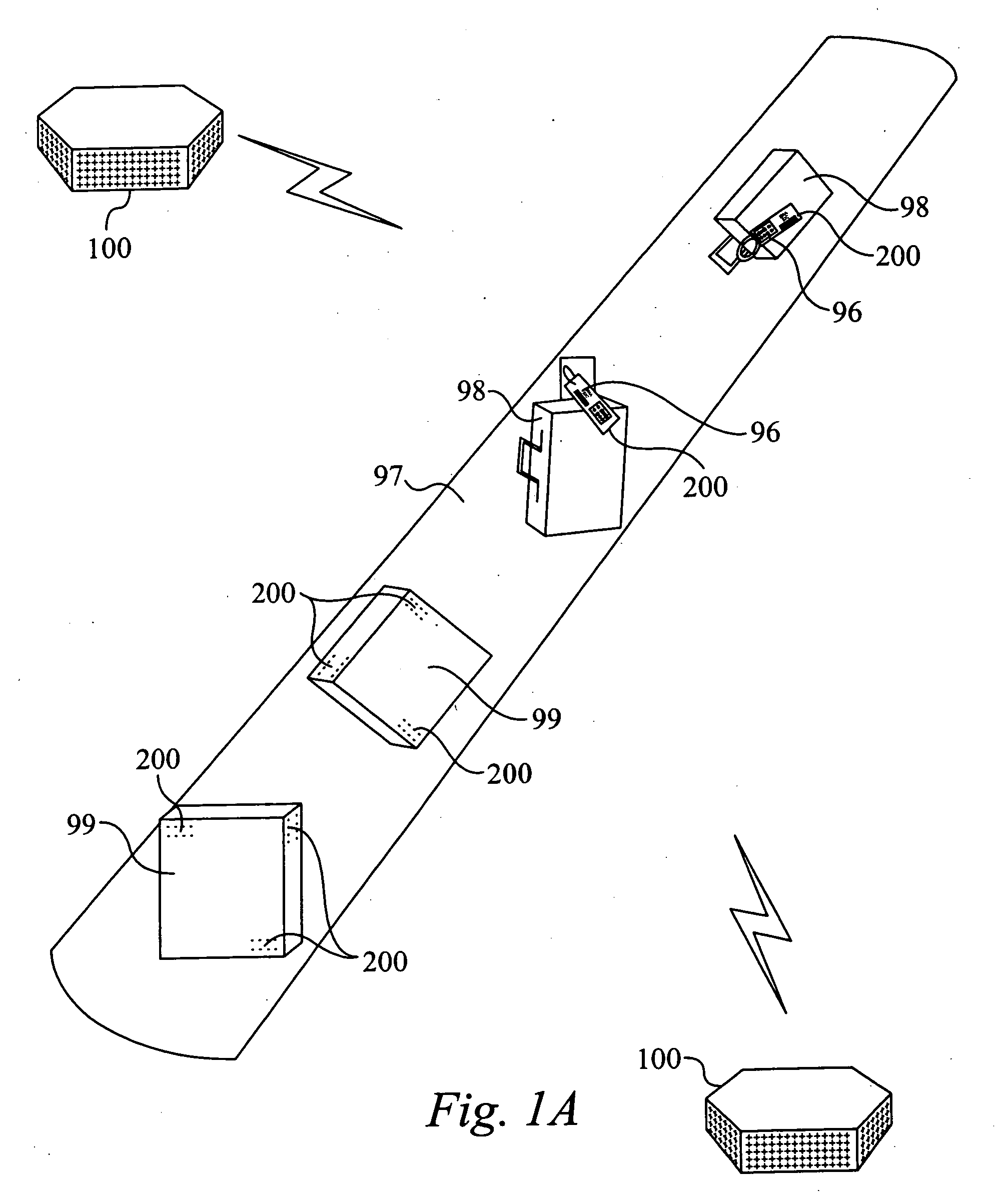
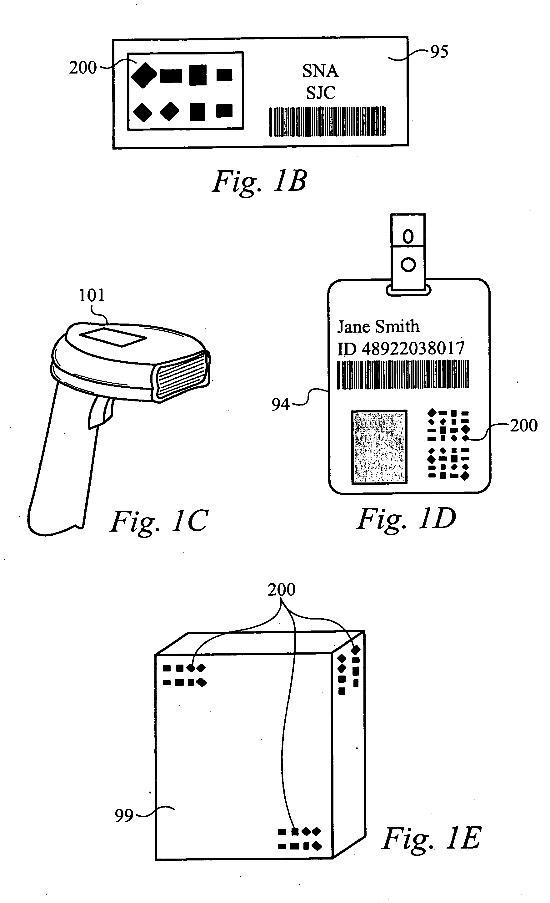
[0025] Embodiments of the present invention are described herein in the context of an RFID system utilizing parametric reflective technology. Those of ordinary skill in the art will realize that the following detailed description of the present invention is illustrative only and is not intended to be in any way limiting. Other embodiments of the present invention will readily suggest themselves to such skilled persons having the benefit of this disclosure. Reference will now be made in detail to implementations of the present invention as illustrated in the accompanying drawings. The same reference indicators will be used throughout the drawings and the following detailed description to refer to the same or like parts.

[0026] The present invention described herein preferably utilizes a very low cost RFID tag construction that does not require semiconductor or chip technologies. The present invention preferably can read the RFID tags at distances up to 100 meters as well as read and ...


PUM


Abstract

A system and method for encoding and decoding information by use of radio frequency antennas. The system includes one or more interrogator devices and RFID data tags. The RFID data tags include a plurality of antenna elements which are formed on a substrate or directly on an object. The antenna elements are oriented and have dimensions to provide polarization and phase information, whereby this information represents the encoded information on the RFID tag. The interrogator device scans an area and uses radar imaging technology to create an image of a scanned area. The device receives re-radiated RF signals from the antenna elements on the data tags, whereby the data tags are preferably represented on the image. The re-radiated RF signals preferably include polarization and phase information of each antenna element, whereby the information is utilized using radar signal imaging algorithms to decode the information on the RF data tag.

Description

STATEMENT OF RELATED APPLICATION(S) [0001] The present application claims priority based on U.S. Provisional Patent Application Ser. No. 60 / 581,384, filed on Jun. 22, 2004, in the name of inventor Michael Gregory Pettus, entitled “Millimeter Wave RFID System Using Parametric Reflective Encoding,” commonly owned herewith, which is hereby incorporated herein by reference.FIELD OF THE INVENTION [0002] The present invention is directly generally to the field of radio frequency identification (RFID) interrogators and data tags as well as encoding and decoding methods. BACKGROUND OF THE INVENTION [0003] There are many existing technologies in current development and deployment that implement the desired function of identifying articles, objects, vehicles and personnel. Bar codes and magnetic strips are traditionally familiar as short range devices. More recently, techniques for increasing the read reliability are being used in the general area of radio frequency identification or RFID. [0...

Claims


Application Information

Patent Timeline
Patent Type & Authority Applications(United States)
IPC IPC(8): G06K7/00G06K19/067G08B13/14H01Q1/22H04Q5/22
CPCG06K19/0672H01Q1/2208H01Q1/22H01Q21/062H01Q21/065H01Q21/245G08B13/2462G01S13/9064G01S13/9076G01S13/751G06K7/00G06K19/067
Inventor PETTUS, MICHAEL GREGORY
Owner VUBIQ
Why Eureka
Try Eureka